
Asynchronous space-time coding metasurface

A space-time encoding and metasurface technology, applied to antennas, electrical components, etc., can solve problems such as inaccessibility, and achieve the effect of simple hardware structure

Pending Publication Date: 2022-06-28
SOUTHEAST UNIV
View PDF0 Cites 0 Cited by
  • Summary
  • Abstract
  • Description
  • Claims
  • Application Information

AI Technical Summary

Problems solved by technology

However, the existing coding metasurfaces are all designed and implemented under the synchronous framework, that is, the dynamic scattering electromagnetic wavefront cannot be obtained.

Method used


Image

  • Asynchronous space-time coding metasurface
  • Asynchronous space-time coding metasurface
  • Asynchronous space-time coding metasurface

Examples


Embodiment 1

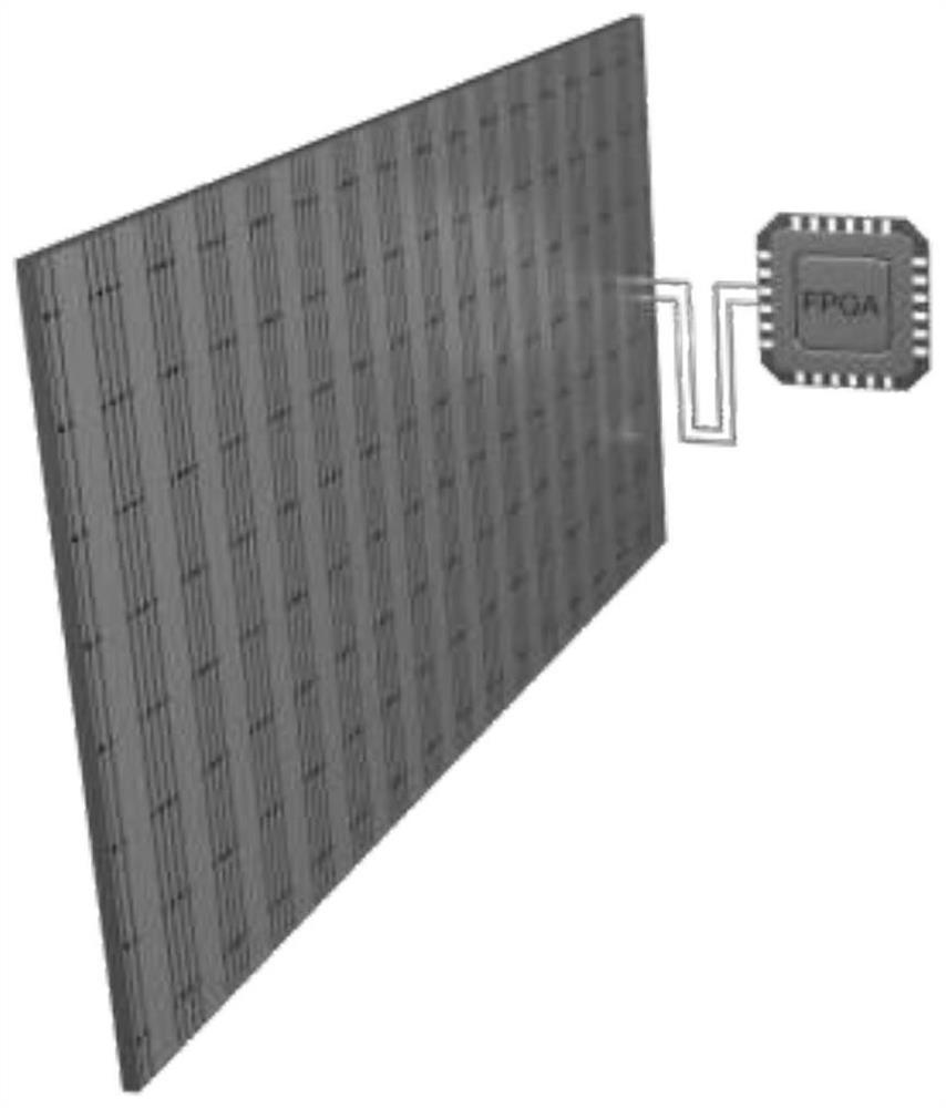
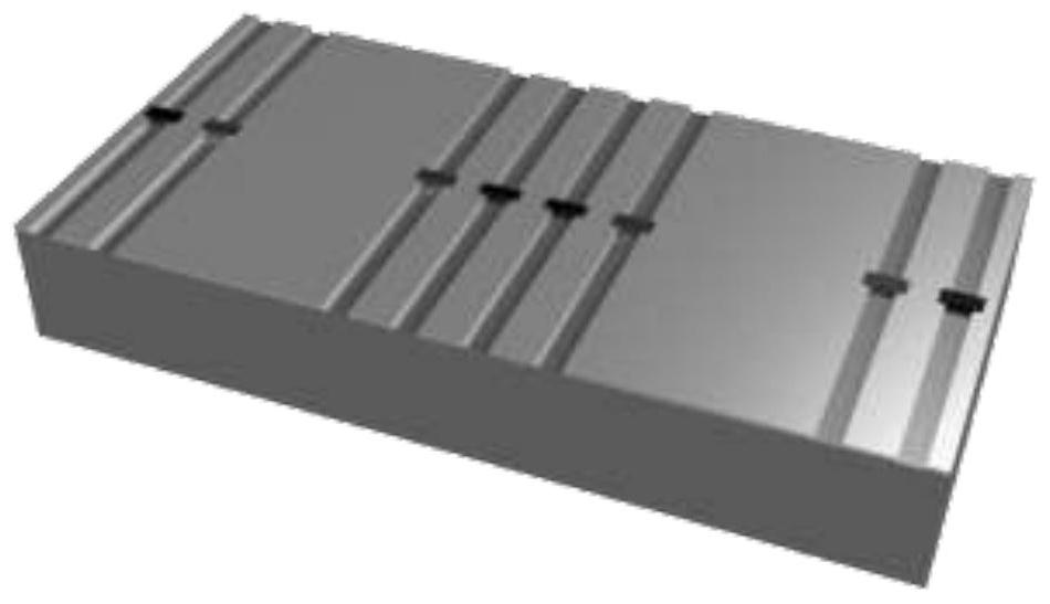
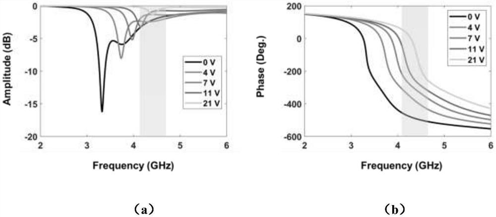
[0029] In the present invention, the asynchronous space-time coding metasurface can be used to realize the automatic spatial scanning of electromagnetic waves. Specifically, using the modulation waveform described above, the modulation time of each column of cells in the coding metasurface is kept unchanged, and the modulation frequency difference between two adjacent columns remains unchanged (that is, the modulation frequency is linear on the array surface). Increase). At this time, the encoding metasurface will maintain a dynamic phase gradient, that is, generate a dynamic spatial scattering pattern, such as Figure 4 shown. Further, by adjusting the modulation frequency difference between two adjacent columns, the speed of the automatic scanning of the electromagnetic wave space can be adjusted. like Figure 5 As shown, when the modulation frequency of two adjacent columns is doubled, the time to complete the automatic scanning of the same space is reduced to half. On ...

Embodiment 2

[0031] In the present invention, the asynchronous space-time encoding metasurface is regarded as a radar target, and its radar cross section (RCS) can be observed to be dynamic. Using the modulation waveform described above and applying different time modulation periods to each column on the coding metasurface at the same time, the coding metasurface can obtain a time-varying RCS. Further, by designing the spatial distribution of the modulation period on the coding metasurface (ie, the spatial coding of the temporal modulation period), the curve characteristics of its time-varying RCS can be effectively controlled. For example, under the condition that the control signal waveform of the entire encoding metasurface remains unchanged, and aiming to reduce the RCS of the asynchronous space-time encoding metasurface in a period of time, the present invention adopts random space encoding for the modulation period, genetic algorithm (GA) Spatial coding, particle swarm optimization (...


PUM


Abstract

The invention discloses an asynchronous space-time coding metasurface. Specifically, by applying control signals with different time periods to different units on the metasurface, a dynamic space electromagnetic wave wavefront can be generated. The method has the beneficial effects that by applying control signals with different time periods to different space units, space electromagnetic waves can be effectively controlled, and a new dimension capable of controlling the electromagnetic waves is developed for the field of artificial electromagnetic metamaterials. Dynamic electromagnetic wave wavefront can be generated and effectively controlled, and therefore space automatic scanning of electromagnetic waves can be achieved. In addition, when the material is used as a radar target, the radar cross-sectional area of the material is time-varying under a static condition, which is not possessed by traditional materials. Under the irradiation of monochromatic electromagnetic waves, multiple frequencies can be generated at will. Compared with a traditional multi-frequency generation system (such as a frequency control array), the system is simple in hardware structure, and does not need related devices such as a local oscillator source.

Description

technical field [0001] The invention relates to an asynchronous space-time coding metasurface, which belongs to the technical field of novel artificial electromagnetic metamaterials. Background technique [0002] The existing space-time encoding metasurface technology can simultaneously design the phase encoding of the unit reflection in space and time, so that the encoding metasurface can obtain the ability to control the wavefront and spectrum of electromagnetic waves at the same time. However, the existing encoding metasurfaces are all designed and implemented under the synchronous framework, that is, the dynamic scattered electromagnetic wave front cannot be obtained. SUMMARY OF THE INVENTION [0003] technical problem: [0004] The technical problem to be solved by the present invention is to provide an encoded metasurface that can generate and control dynamic electromagnetic wave fronts. The specific implementation method is to apply modulation signals with differe...

Claims


Application Information

Patent Timeline
IPC IPC(8): H01Q15/00
CPCH01Q15/0086H01Q15/00
Inventor 程强王思然崔铁军
Owner SOUTHEAST UNIV
Learn More