Hot rolling process of non-oriented silicon steel

An oriented silicon steel and process technology, applied in the direction of metal rolling, metal rolling stand, metal rolling mill stand, etc., can solve the problem of non-oriented silicon steel strip head narrowing, etc., to prevent the end from widening. The effect of large, reduced width deviation, and reduced trimming amount

Pending Publication Date: 2022-07-01
ANYANG IRON & STEEL +1
View PDF11 Cites 0 Cited by
  • Summary
  • Abstract
  • Description
  • Claims
  • Application Information

AI Technical Summary

Problems solved by technology

This method is mainly implemented in the dynamic adjustment during the rolling process. A large part of the narrowing of the head during the hot rolling of the non-oriented silicon steel strip is due to the small influence of the narrowing formed during the tension building process during biting, which cannot solve the problem. The head of the oriented silicon steel strip is narrowed during hot rolling. For this reason, we propose a hot rolling process of non-oriented silicon steel to solve the above problem

Method used


Image

  • Hot rolling process of non-oriented silicon steel
  • Hot rolling process of non-oriented silicon steel
  • Hot rolling process of non-oriented silicon steel

Examples


Embodiment 1

[0037] refer to figure 1 As shown, a kind of hot rolling process of non-oriented silicon steel, the specific steps are as follows:

[0038] Step 1: The mass percentage of the main chemical components of the billet is C: 0.0026; Si: 0.61; Mn: 0.41; P: 0.015; Al: 0.15; others are Fe and inevitable impurity elements. According to empirical formula A r3 =901-325C-92Mn+33Si+287P+40Al-20Cr Calculated A r3 =893°C.

[0039] Step 2: The temperature of the slab entering the furnace is 630°C, and the heating temperature of the slab is 1160°C;

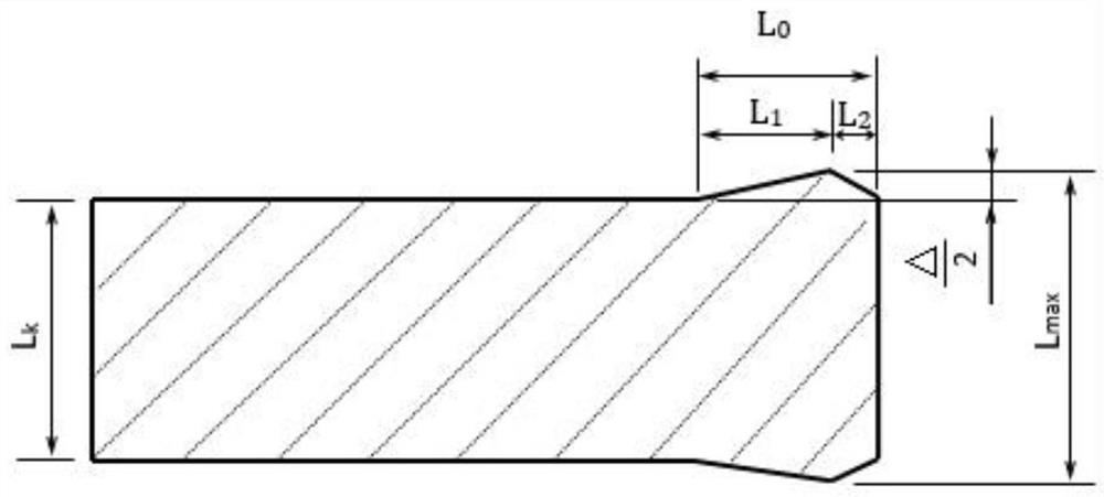
[0040] Step 3: The deformation rate of the last pass of the rough rolling mill is 33.3%, the rolling temperature is 1038°C, the thickness of the intermediate billet is 43mm, and the width of the intermediate billet is L k =1050mm, blank width is 1080mm, intermediate blank vertical roll width reduction is 30mm, set L 0 =8000mm, L 2 =400mm, L 1 =L 0 -L 2 =7600mm. During rolling, the L 2 The vertical roll gap in the length range is defined...

Embodiment 2

[0046] refer to figure 1 As shown, a kind of hot rolling process of non-oriented silicon steel, the specific steps are as follows:

[0047] Step 1: The mass percentage of the main chemical components of the billet is C: 0.0021; Si: 1.35; Mn: 0.43; P: 0.018; Al: 0.27; others are Fe and inevitable impurity elements. According to empirical formula A r3 =901-325C-92Mn+33Si+287P+40Al-20Cr Calculated A r3 =921°C.

[0048] Step 2: The temperature of the slab entering the furnace is 610°C, and the heating temperature of the slab is 1150°C;

[0049] Step 3: The deformation rate of the last pass of the rough rolling mill is 33.3%, the rolling temperature is 1035 ° C, the thickness of the intermediate billet is 42 mm, and the width of the intermediate billet is L k =1250mm, blank width is 1270mm, intermediate blank vertical roll width reduction is 20mm, set L 0 =12000mm, L 2 =400mm, L 1 =L 0 -L 2 =11600mm. During rolling, the L 2 The vertical roll gap in the length range is de...


PUM


Abstract

The invention discloses a hot rolling process of non-oriented silicon steel. Aiming at the phenomenon that the width of the head of a plate strip within 100m in the finish rolling process is easily narrowed in the finish rolling process due to small deformation resistance in the hot rolling process of non-oriented silicon steel, an intermediate billet width compensation amount model is established according to main factors such as chemical components, rolling temperature and rack tension, and the intermediate billet width compensation amount is calculated according to the model. And meanwhile, a short-stroke control method of the vertical roller is combined, so that the purpose of reducing the width difference of the through roll is achieved. And the width difference of the whole roll is reduced from 30mm to below 15mm, and the edge cutting amount and the head and tail loss are reduced.

Description

technical field [0001] The invention relates to the technical field of silicon steel production, in particular to a hot rolling process of non-oriented silicon steel. Background technique [0002] Non-oriented silicon steel is mainly used in the manufacture of motor cores. With the development of electrification, the amount of non-oriented silicon steel is increasing. However, in the production process of non-oriented silicon steel, it is found that in the process of hot rolling, due to the low deformation resistance of high temperature silicon steel, the width of the steel strip will be narrowed during the construction of the finishing mill, which is manifested as a reduction in the width of the strip head within 100m. The small amount reaches 25mm, and the width deviation of the through roll reaches 30mm, which seriously affects the yield of finished products. [0003] The Chinese patent document of Patent Application No. 201210566715.4, which discloses "parameter compens...

Claims


Application Information

Patent Timeline
Patent Type & Authority Applications(China)
IPC IPC(8): B21B37/22B21B1/22
CPCB21B37/22B21B1/22
Inventor 孔德南牛庆林邓杭州欧阳瑜商存亮王新志黄重徐党委陈冬至饶静陈全杨立庆张苓志马俊华肖彦忠
Owner ANYANG IRON & STEEL
Why Eureka
Try Eureka