
Construction method for erecting simply supported steel beams at circulating floating transport bridge site

A construction method and bridge position technology, which is applied in the direction of erecting/assembling bridges, bridges, bridge construction, etc., can solve the problems of movable bearings losing part of their effectiveness, movable bearings deviating from the designed position, and difficulty in setting temporary supports, etc., to achieve construction operation Low difficulty, reduced cantilever length, and simple construction

Pending Publication Date: 2022-07-01
SHIJIAZHUANG TIEDAO UNIV
View PDF0 Cites 0 Cited by
  • Summary
  • Abstract
  • Description
  • Claims
  • Application Information

AI Technical Summary

Problems solved by technology

[0003] If simply supported beams are constructed by the bracket method at the pier position, a large number of temporary support structures will be used, and the required labor and material costs are high. In most cases, it is not easy to set up temporary supports at the bridge pier position; During the process, the simply supported beam needs to be converted into a continuous structure first, and then the jacking is carried out. After the jacking is in place, it is necessary to carry out the system conversion of continuous variable simple support and drop the beam. The system conversion steps are complicated, the construction operation is difficult, and the beam drop The safety risk is high, and the setting of the push slideway needs to occupy a large area of ​​the construction site; the cantilever construction needs to consider the need to set up temporary supports of more than half a span during the assembly process, and at the same time, it is necessary to perform system conversion from simply supported to continuous and from continuous to simply supported. , there is the problem of falling beams and considering the problem of deflection in the assembly process
[0004] If the floating method is used, it is often necessary to assemble the steel truss girders on the shore and transport them to the bridge site through semi-submersible ships and other equipment. If high-level transportation is used, the overall center of gravity will be relatively high during the transportation process. This process is easy to capsize and poses a risk It is relatively large, and after being transported in place, high-level drop beams have high requirements for construction technology and there are many restrictions; for example, low-level floating transportation can reduce the overall center of gravity, but there are still a series of problems in lifting beams, shifting and dropping beams after they are in place, and need Add a lot of large beam lifting equipment
[0005] And at present, when the falling beam is installed, there is also a huge problem in the installation of the movable support, because the upper pendulum and the hem of the movable support need to be able to move relatively, and in order to facilitate installation, the existing method is to place the movable support in the factory. The upper hem and the lower hem are directly connected with connecting rods, and then installed on the steel beam. After the steel beam falls, the lower hem of the movable support is installed on the bridge pier. Since the construction temperature is often different from the design temperature, the shrinkage of the steel beam Will cause the movable support to deviate from the design position, causing the movable support to lose part of its effectiveness

Method used


Image

  • Construction method for erecting simply supported steel beams at circulating floating transport bridge site
  • Construction method for erecting simply supported steel beams at circulating floating transport bridge site
  • Construction method for erecting simply supported steel beams at circulating floating transport bridge site

Examples


Embodiment Construction

[0048] In order to make the technical problems, technical solutions and beneficial effects to be solved by the present invention clearer, the present invention will be further described in detail below with reference to the accompanying drawings and embodiments. It should be understood that the specific embodiments described herein are only used to explain the present invention, but not to limit the present invention.

[0049] Now, the construction method for erecting a simply supported steel girder on a circulating floating bridge provided by the present invention will be described.

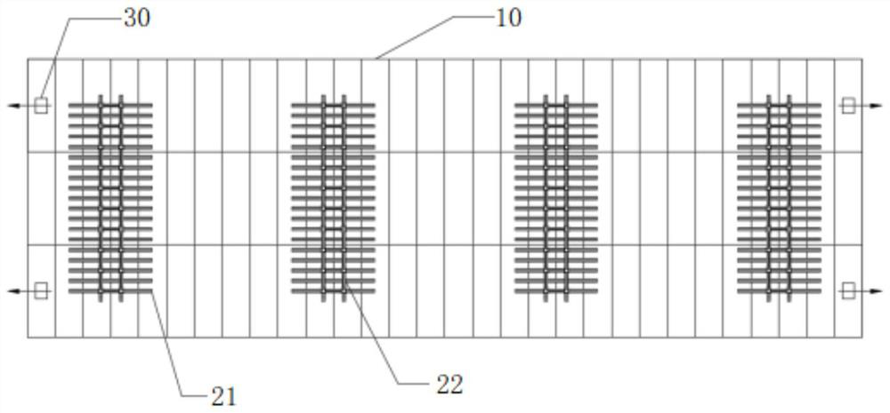
[0050] Please also refer to Figure 1 to Figure 11 , the construction method for erecting a simply supported steel beam on a circulating floating bridge provided by the first embodiment of the present invention includes:

[0051] 1. Assemble the floating body 10, use a floating box to assemble the floating body 10 on the shore, then assemble the temporary buttress 20 on the floating body 10, an...


PUM


Abstract

The invention provides a construction method for erecting a simply supported steel beam at a circulating floating transport bridge site, which belongs to the technical field of bridge construction and comprises the steps of floating body assembly, pre-assembly and hoisting of a steel truss girder member, transportation in place, steel truss girder assembly, installation of the steel truss girder and a support, separation of the floating body and the steel truss girder and the like. A circulating floating transportation method is adopted, the overall gravity center can be lowered to the minimum, and therefore the requirement for equipment and the construction risk are lowered, the problem of installation of an existing movable support can be solved, system transformation and supports are not needed, safety is better guaranteed, circulating erection can be achieved, and the construction period can be shortened.

Description

technical field [0001] The invention belongs to the technical field of bridge construction, and more particularly relates to a construction method for erecting simply supported steel beams on a circulating floating bridge position. Background technique [0002] With the development of bridge construction, the bridge construction environment has become complex and diverse. Usually, corresponding construction methods need to be adopted according to different construction environments. Generally, there are four main construction methods for steel truss beams: support method, jacking method method, cantilever method and floatation method. [0003] If the simply supported beam is constructed by the support method at the pier position, a large number of temporary support structures need to be used, and the labor and material costs are relatively high, and in most cases, it is difficult to set temporary support at the bridge pier position; In the process, the simply supported beam...

Claims


Application Information

Patent Timeline
Patent Type & Authority Applications(China)
IPC IPC(8): E01D21/00E01D4/00E01D6/00B63B75/00
CPCE01D21/00E01D4/00E01D6/00B63B75/00
Inventor 向敏马佳硕吴聪杨从娟杨惠高明慧滕培松张露锋詹钦鹏宋炳功
Owner SHIJIAZHUANG TIEDAO UNIV
Learn More