Supercharge Your Innovation With Domain-Expert AI Agents!

Winding mutual compensation structure of coupling resonant excitation system of brushless electro-magnetic synchronous motor

A synchronous motor, coupled resonance technology, which is applied in the control of wound excitation motors, control systems, AC motor control, etc., can solve problems such as unfavorable power density improvement, difficult installation, and increase in size, and achieve convenient and reliable implementation. , The effect of reducing loss size and improving reliability

Pending Publication Date: 2022-07-01
HARBIN INST OF TECH
View PDF0 Cites 0 Cited by
  • Summary
  • Abstract
  • Description
  • Claims
  • Application Information

AI Technical Summary

Problems solved by technology

Since the system multiplexes the stator armature winding as the transmitting inductance, in order to ensure the constant transmission frequency in the original end resonant compensation topology, the compensation inductance and the armature winding inductance are required to be equal in size, and the inductance of the stator armature winding in the motor is generally large, and in addition Adding compensation inductance will increase the size, it is not easy to install with the motor, and it is not conducive to the increase of power density
[0004] In order to solve the above problems, this patent is proposed: a brushless electric excitation synchronous motor coupled resonant excitation system winding mutual compensation structure, the stator armature winding is divided into sections and equal parts, each section can be used as a transmitting inductance and realize mutual compensation, no need Add compensation inductance, there are no problems such as large volume, difficult to install in the motor, etc.

Method used


Image

  • Winding mutual compensation structure of coupling resonant excitation system of brushless electro-magnetic synchronous motor
  • Winding mutual compensation structure of coupling resonant excitation system of brushless electro-magnetic synchronous motor
  • Winding mutual compensation structure of coupling resonant excitation system of brushless electro-magnetic synchronous motor

Examples


Embodiment Construction

[0039] The technical solutions in the embodiments of the present invention will be clearly and completely described below with reference to the drawings in the embodiments of the present invention. Obviously, the described embodiments are only a part of the embodiments of the present invention, but not all of the embodiments. Based on the embodiments of the present invention, all other embodiments obtained by those of ordinary skill in the art without creative efforts shall fall within the protection scope of the present invention.

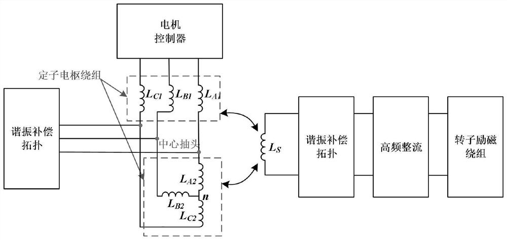
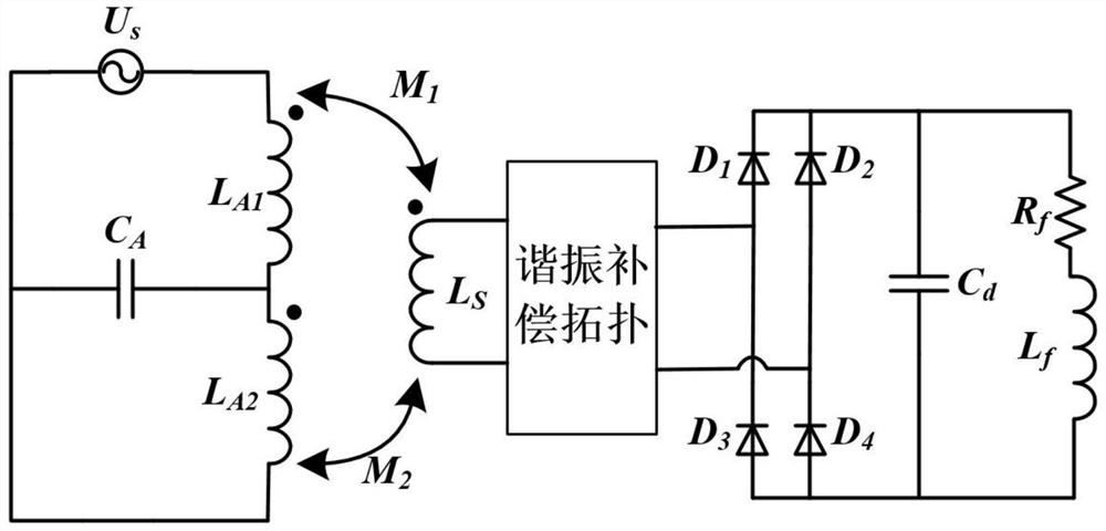
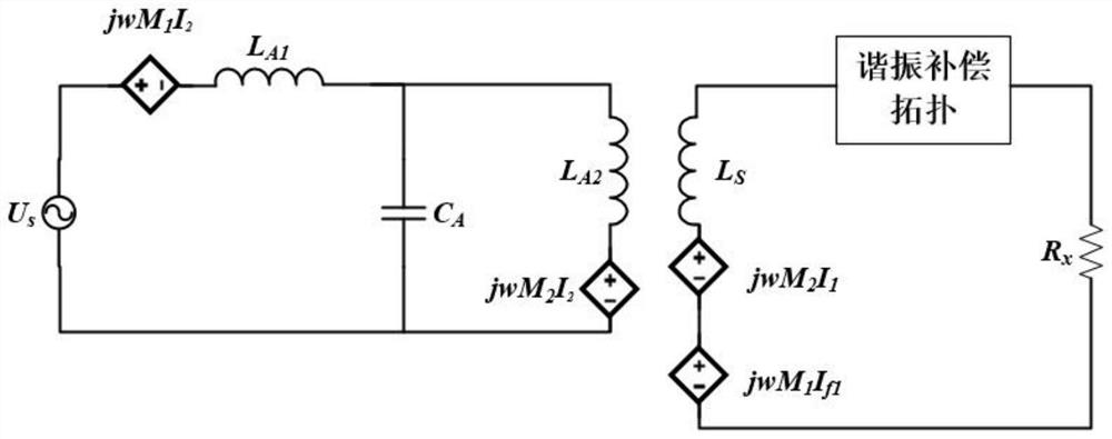
[0040] combine Figure 1 to Figure 7 .

[0041]Aiming at the resonant coupling wireless excitation synchronous motor system, the invention reuses the armature windings again on the basis of the multiplexed stator armature winding as the transmitting inductance, and divides them into equal parts as the compensation inductance and the transmitting inductance in the resonant network topology. The dual coupling system realizes dual emission and mutua...


PUM


Abstract

The invention provides a winding mutual compensation structure of a coupling resonant excitation system of a brushless electro-magnetic synchronous motor. The winding mutual compensation structure comprises a primary side circuit and a secondary side circuit, the primary side circuit comprises a first resonance compensation topology, a motor controller and a stator armature winding system; the secondary circuit comprises a secondary receiving inductor, a second resonance compensation topology, a high-frequency rectification unit and a rotor excitation winding; the first resonance compensation topology is connected with the stator armature winding system and is controlled by the motor controller; the secondary receiving inductor, the second resonance compensation topology, the high-frequency rectification unit and the rotor excitation winding are connected in sequence, and the secondary receiving inductor, the second resonance compensation topology, the high-frequency rectification unit and the rotor excitation winding are connected in sequence. The inductor is equally divided to serve as a compensation inductor and a transmitting inductor in the resonance network topology, and a double-coupling system is constructed to realize double transmission and mutual compensation, so that an external compensation inductor is omitted, and the size of the system is reduced.

Description

technical field [0001] The invention relates to the field of an excitation method for an electric excitation synchronous motor and the field of wireless power transmission, in particular to a structure for mutual compensation of windings of a brushless electric excitation synchronous motor coupled resonant excitation system. Background technique [0002] In the field of electric vehicles and other drive motors, permanent magnet synchronous motors have developed rapidly due to high power density applications, but they have problems such as unadjustable permanent magnet magnetic fields, limited field weakening working areas, shortage of rare earth resources, and high prices. The low-speed torque is larger, the high-speed constant power range is wider, and the efficiency is higher, which is more in line with the higher speed expansion ratio and lower cost required by electric vehicles. But a major problem with electrically excited synchronous motors is the need to use slip ring...

Claims


Application Information

Patent Timeline
Patent Type & Authority Applications(China)
IPC IPC(8): H02P6/32H02P25/03H02P25/16H02P25/22H02J50/12
CPCH02P6/32H02P25/03H02P25/16H02P25/22H02J50/12H02P2207/05
Inventor 张玉琦高鑫赵天旭王清崔淑梅
Owner HARBIN INST OF TECH
Features
  • R&D
  • Intellectual Property
  • Life Sciences
  • Materials
  • Tech Scout
  • Unparalleled Data Quality
  • Higher Quality Content
  • 60% Fewer Hallucinations
Learn More