Continuous fiber reinforced thermoplastic composite board as well as preparation method and production equipment thereof

A technology for reinforcing thermoplastic and continuous fibers, applied in chemical instruments and methods, layered products, metal layered products, etc., can solve the problems of uneven bonding strength of sheet composites and cannot be heated, and achieve uniform heating surface and high production. The effect of speed, high composite strength

Pending Publication Date: 2022-07-05
JIANGSU QIYI TECH
View PDF0 Cites 0 Cited by
  • Summary
  • Abstract
  • Description
  • Claims
  • Application Information

AI Technical Summary

Problems solved by technology

Traditional continuous Teflon lamination equipment or steel belt lamination equipment has a relatively uniform heating surface, which cannot selectively heat different areas of the plate, resulting in uneven bonding strength of the plate.

Method used


Image

  • Continuous fiber reinforced thermoplastic composite board as well as preparation method and production equipment thereof
  • Continuous fiber reinforced thermoplastic composite board as well as preparation method and production equipment thereof
  • Continuous fiber reinforced thermoplastic composite board as well as preparation method and production equipment thereof

Examples


Embodiment 1

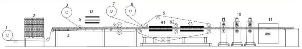
[0040] see figure 1 , the lower layer unwinding device 1 is arranged at the front end of the equipment, unwinds the lower layer, the honeycomb core placement platform 2 puts the honeycomb core to the top of the lower layer, and the lower layer unwinding device 1 is located on the left side of the honeycomb core placement platform 2 On the side, the honeycomb core conveying platform 4 is arranged under the lower surface layer, the honeycomb core conveying platform 4 drives the lower surface layer and the honeycomb core to move as a whole, and the lower adhesive film unwinding device 3 unwinds the lower adhesive film and presses the lower adhesive film to cover the surface of the honeycomb core. , the lower film unwinding device 3 is located on the left side of the steel plate placing device 5, the steel plate placing device 5 is located above the honeycomb core, and is in the same position as the steel plate heating device 12, and the rolling device 6 is arranged on the left sid...

Embodiment 2

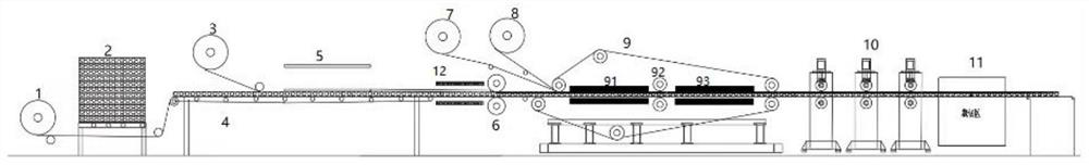
[0042] see figure 2 , the lower layer unwinding device 1 is arranged at the front end of the equipment, unwinds the lower layer, the honeycomb core placement platform 2 puts the honeycomb core to the top of the lower layer, and the lower layer unwinding device 1 is located on the left side of the honeycomb core placement platform 2 On the side, the honeycomb core conveying platform 4 is arranged under the lower surface layer, the honeycomb core conveying platform 4 drives the lower surface layer and the honeycomb core to move as a whole, and the lower adhesive film unwinding device 3 unwinds the lower adhesive film and presses the lower adhesive film to cover the surface of the honeycomb core. , the lower film unwinding device 3 is located on the left side of the steel plate placing device 5, the steel plate placing device 5 is located above the honeycomb core, the steel plate heating device 12 is arranged on the right side of the steel plate placing device 5, and the rolling ...

Embodiment 3

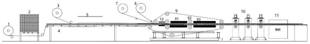
[0044] see image 3 , the lower layer unwinding device 1 is arranged at the front end of the equipment, unwinds the lower layer, the honeycomb core placement platform 2 puts the honeycomb core to the top of the lower layer, and the lower layer unwinding device 1 is located on the left side of the honeycomb core placement platform 2 On the side, the honeycomb core conveying platform 4 is arranged under the lower surface layer, the honeycomb core conveying platform 4 drives the lower surface layer and the honeycomb core to move as a whole, and the lower adhesive film unwinding device 3 unwinds the lower adhesive film and presses the lower adhesive film to cover the surface of the honeycomb core. , the lower film unwinding device 3 is located on the left side of the steel plate placing device 5, the steel plate placing device 5 is located above the honeycomb core, the steel plate heating device 12 is arranged on the right side of the steel plate placing device 5, and the rolling d...


PUM


Abstract

The invention mainly relates to the field of composite material processing, in particular to a continuous fiber reinforced thermoplastic composite plate as well as a preparation method and production equipment thereof. The preparation method of the continuous fiber reinforced thermoplastic composite board mainly comprises the following steps: placing a steel plate on the left side of a rolling device, and heating the steel plate in advance by a steel plate heating device to preheat a steel plate adhesive film to a molten state; the rolling device is used for pressing and cooling the composite structure so as to quickly bond the molten adhesive film on the surface of the steel plate or the honeycomb core; and heating, pressing and cooling the surface layer of the composite structure by using a compound machine device to form the continuous fiber reinforced thermoplastic composite board, the material product prepared by the method is flat and attractive in surface, high in composite strength and high in compression strength, and the composite board is good in impact resistance and puncture resistance.

Description

technical field [0001] The invention relates to the field of composite material processing, in particular to a continuous fiber reinforced thermoplastic composite board and a preparation method and production equipment thereof. Background technique [0002] Continuous fiber reinforced thermoplastic composite materials have the characteristics of light weight, high strength, heat insulation, etc., and are more and more widely used in the field of composite materials. Traditional battery pack protective plates are made of full-size steel plates, but the proportion of steel is large and the price is high, which cannot be satisfied. Lightweight demand for new energy vehicles. At present, the protective panels are also made of continuous thermoplastic honeycomb panels, but the thermoplastic honeycomb panels have poor impact performance and puncture resistance. If they encounter sharp objects, such as sharp stones, nails, steel wires or iron wires on the road, they are easily pier...

Claims


Application Information

Patent Timeline
Patent Type & Authority Applications(China)
IPC IPC(8): B32B15/18B32B15/04B32B3/12B32B33/00B32B7/12B32B37/06B32B37/10B32B37/12B32B37/08B32B38/00
CPCB32B15/18B32B15/04B32B3/12B32B33/00B32B7/12B32B37/06B32B37/10B32B37/1207B32B37/08B32B38/0004B32B2037/1223
Inventor 朱华平李要山
Owner JIANGSU QIYI TECH
Why Eureka
Try Eureka