Unmanned aerial vehicle and catapult thereof

A technology of drones and catapults, applied in the field of drones, can solve the problems of large space occupation, inconvenient transfer process, and restrictions on the flight conditions of drones, so as to extend the flight track, reduce the occupied space, and ensure ejection effect of effect

Pending Publication Date: 2022-07-05
黄嘉伟
View PDF0 Cites 0 Cited by
  • Summary
  • Abstract
  • Description
  • Claims
  • Application Information

AI Technical Summary

Problems solved by technology

[0003] However, traditional fixed-wing UAVs take up a lot of space, and the transfer process is extremely inconvenient, and the traditional ejection racks that perform ejection tasks generally need to be placed on the ground for ejection tasks, and the ejection parts need to be hoisted to the ground for deployment separately, extending the The flight preparation time and the need to select a flat ground to perform the launch mission strictly limit the flight conditions of the UAV; The device is easily corroded under long-term exposure to the sun or wind and rain, and cannot protect the drone and ejection parts, thereby reducing the ability to use the drone in response to emergencies, and the existing ejection There is no blocking shield on the frame, which reduces the service life of the catapult

Method used


Image

  • Unmanned aerial vehicle and catapult thereof
  • Unmanned aerial vehicle and catapult thereof
  • Unmanned aerial vehicle and catapult thereof

Examples


Embodiment Construction

[0031] In order to make it easy to understand the technical means, creation features, achieved goals and effects of the present invention, the present invention will be further described below with reference to the specific embodiments.

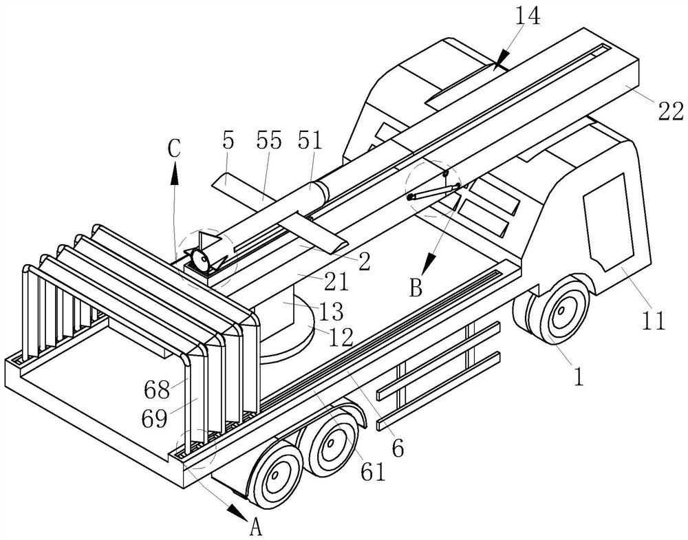
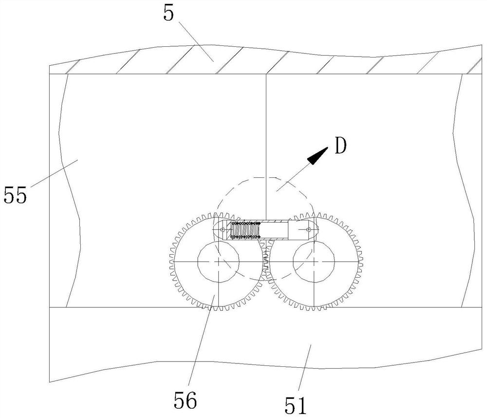
[0032] like Figure 1-Figure 9As shown, an unmanned aerial vehicle and its catapult according to the present invention include a flight mechanism 5, and the flight mechanism 5 includes a body 51. The body 51 is provided with a support plate 53, and the upper part of the support plate 53 is provided. A plurality of rollers 54 are installed, three tail wings 52 are installed on the body 51, and two flying wings 55 are rotated on the body 51, and a second gear 56 is arranged on the flying wings 55. The two gears 56 are rotatably connected in the body 51 and mesh with each other. A first telescopic rod 57 and a second telescopic rod 58 are rotated between the two second gears 56 . The first telescopic rod 57 and the second telescopic rod 58 Slid...


PUM


Abstract

The invention relates to the technical field of unmanned aerial vehicles, in particular to an unmanned aerial vehicle and a catapult thereof.The unmanned aerial vehicle comprises a flight mechanism, a catapulting mechanism is arranged on the flight mechanism, a folding mechanism is arranged on the catapulting mechanism, a power mechanism is installed between the folding mechanism and the catapulting mechanism, and the power mechanism drives the catapulting mechanism; a placement mechanism is rotationally arranged on the folding mechanism, and a shielding mechanism is arranged on the placement mechanism; through the arrangement of the flight mechanism, wings of the unmanned aerial vehicle can be folded and stored conveniently, the placement mechanism can transport the unmanned aerial vehicle conveniently, and the occupied space of the unmanned aerial vehicle is reduced; the folding mechanism and the flight mechanism are convenient to carry to move through the arrangement of the placement mechanism, the unfolded folding mechanism is convenient to support, and the flight track is convenient to extend through the arrangement of the folding mechanism, so that the flight mechanism obtains enough acceleration; and through the arrangement of the shielding mechanism, auxiliary parts of the flight mechanism can be shielded and protected conveniently, and the outdoor viability of the unmanned aerial vehicle and the launcher is improved.

Description

technical field [0001] The invention relates to the technical field of unmanned aerial vehicles, in particular to an unmanned aerial vehicle and a catapult thereof. Background technique [0002] Unmanned aircraft, referred to as "UAV", is an unmanned aircraft that is operated by radio remote control equipment and self-provided program control devices, or is operated completely or intermittently by an on-board computer. Compared to manned aircraft, drones are often better suited for missions that are too "dumb, dirty, or dangerous". The initial flight of the drone needs to be able to fly, and for this reason, the flight mission needs to be A catapult that uses acceleration. [0003] However, traditional fixed-wing UAVs take up a lot of space, and the transfer process is extremely inconvenient, and traditional ejection racks that perform ejection tasks generally need to be placed on the ground for ejection tasks. The flight preparation time, and the need to select a flat gro...

Claims


Application Information

Patent Timeline
Patent Type & Authority Applications(China)
IPC IPC(8): B64C3/56B64F1/06B64F1/22B64F1/00
CPCB64C3/56B64F1/06B64F1/227B64F1/005
Inventor 黄嘉伟张煜
Owner 黄嘉伟
Why Eureka
Try Eureka