Automatic slot inserting device for glass cleaning and using method of automatic slot inserting device

A glass cleaning and slotting technology, which is applied in the direction of transportation and packaging, conveyor objects, etc., can solve the problems of low batch production speed, low degree of automation, and low efficiency of manual slotting, and achieve the effect of improving slotting efficiency

Pending Publication Date: 2022-07-05
湖南晶讯光电股份有限公司
View PDF0 Cites 0 Cited by
  • Summary
  • Abstract
  • Description
  • Claims
  • Application Information

AI Technical Summary

Problems solved by technology

[0004] In view of this, the present invention provides an automatic slotting device for glass cleaning in order to solve the problems of low efficiency of manual slotting, low batch production speed and low degree of automation in the prior art

Method used


Image

  • Automatic slot inserting device for glass cleaning and using method of automatic slot inserting device
  • Automatic slot inserting device for glass cleaning and using method of automatic slot inserting device
  • Automatic slot inserting device for glass cleaning and using method of automatic slot inserting device

Examples


Embodiment 1

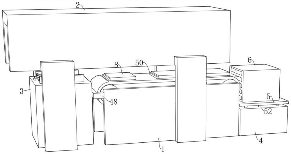
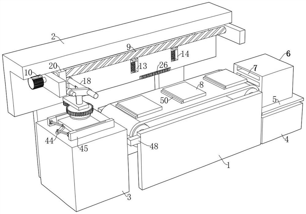
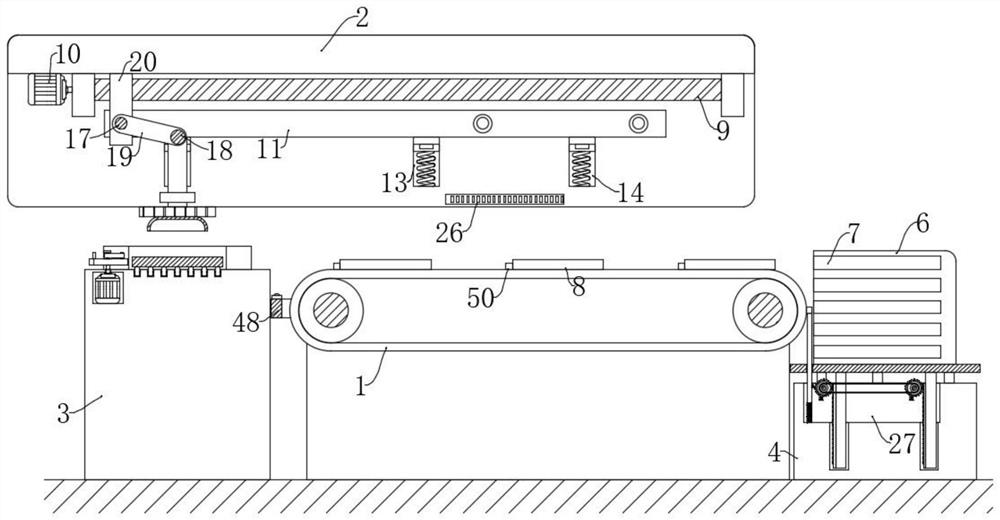
[0050] like Figure 1-11 The shown automatic slot device for glass cleaning includes a conveyor belt 1 and a glass 8 located on the conveyor belt 1, a U-shaped frame 2 is arranged above the conveyor belt 1, and fixed tables are respectively provided at both ends of the conveyor belt 1. 3 and the lifting platform 4, a lifting plate 5 is arranged on the top of the lifting platform 4, a slot frame 6 is placed on the top of the lifting plate 5, and a plurality of slots 7 are arranged on the side of the slot frame 6 close to the conveyor belt 1. There is a transmission groove 27, and the U-shaped frame 2 is provided with a conveying assembly for conveying the glass 8 on the top of the fixed table 3 to the conveyor belt 1, and the top of the fixed table 3 is provided with a glass 8 for adjusting the parallelism of the top of the fixed table 3. Adjustment assembly, the transmission groove 27 is provided with a lifting assembly for intermittently lifting the groove frame 6, the top of...

Embodiment 2

[0059] This embodiment is a further improvement of the previous embodiment, such as Figure 1-12 As shown, an automatic slot device for glass cleaning includes a conveyor belt 1 and a glass 8 located on the conveyor belt 1, a U-shaped frame 2 is arranged above the conveyor belt 1, and a fixed table is provided at both ends of the conveyor belt 1. 3 and the lifting platform 4, a lifting plate 5 is arranged on the top of the lifting platform 4, a slot frame 6 is placed on the top of the lifting plate 5, and a plurality of slots 7 are arranged on the side of the slot frame 6 close to the conveyor belt 1. There is a transmission groove 27, and the U-shaped frame 2 is provided with a conveying assembly for conveying the glass 8 on the top of the fixed table 3 to the conveyor belt 1, and the top of the fixed table 3 is provided with a glass 8 for adjusting the parallelism of the top of the fixed table 3. Adjustment assembly, the transmission groove 27 is provided with a lifting asse...


PUM


Abstract

The invention relates to an automatic slot device for glass cleaning and a using method thereof, and belongs to the technical field of liquid crystal glass processing.The automatic slot device comprises a conveying belt and glass located on the conveying belt, a U-shaped frame is arranged above the conveying belt, a fixing table and a lifting table are arranged at the two ends of the conveying belt respectively, and a lifting plate is arranged at the top of the lifting table; according to the glass conveying device, the rotating motor can be started to drive the rotating plate to rotate, so that the parallelism of glass can be kept, in addition, the driving motor is started to drive the threaded rod to rotate forwards and backwards, and the glass can be conveyed to the conveying belt through the groove frame. The glass conveying device can convey glass and can be matched with the first rack to adjust the direction of the glass, so that the glass is inserted into the insertion groove in the unified direction, manual operation is not needed, automation is improved, the insertion groove efficiency is improved, and the batch production speed is further increased.

Description

technical field [0001] The invention belongs to the technical field of liquid crystal glass processing, and relates to an automatic slot device for glass cleaning and a use method thereof. Background technique [0002] During the processing of liquid crystal glass, only the cleaned glass substrate can be introduced into the packaging process for finished product packaging, storage or delivery. The cleaning effect of the glass substrate is mainly determined by measuring the amount of dust particles attached to the surface of the cleaned substrate. The lower the number of particles , The better the cleaning effect, the better the quality of the finished product. [0003] In the production of liquid crystal displays, the glass needs to be cleaned before the polarizer is attached, and it needs to be inserted into a special slot frame when cleaning. Fast production, and slot work often requires staff to slot glass one by one. Manual operation alone cannot adapt to large-scale gl...

Claims


Application Information

Patent Timeline
Patent Type & Authority Applications(China)
IPC IPC(8): B65G47/46B65G47/91
CPCB65G47/46B65G47/91
Inventor 黄非李文
Owner 湖南晶讯光电股份有限公司
Why Eureka
Try Eureka