Efficient slag treatment device for high-temperature slag waste heat recovery

A technology of waste heat recovery and treatment device, applied in the field of high temperature slag treatment, can solve the problems of reducing waste heat recovery effect, reducing recovery efficiency, reducing resource utilization rate, etc., so as to improve convenience, slow down heat loss, and improve waste heat recovery efficiency. Effect

Active Publication Date: 2022-07-05
NANJING HUADIAN ENERGY SAVING & ENVIRONMENTAL PROTECTION EQUIP
View PDF6 Cites 0 Cited by
  • Summary
  • Abstract
  • Description
  • Claims
  • Application Information

AI Technical Summary

Problems solved by technology

[0007] The purpose of the present invention is to solve the shortcomings in the prior art, such as: the existing high-efficiency slag processing device for high-temperature slag waste heat recovery cannot When the slag is introduced, the temperature on the slag is quickly dissipated, which reduces the recovery efficiency. At the same time, when the slag is introduced, the material guide port is always open, and the heat emitted by the slag is easy to flow from the material guide port. Distributed to the air, resulting in the loss of heat recovery effect, it is inconvenient to recycle the heat energy of slag in a timely manner, resulting in the easy loss of waste heat of slag, the waste heat cannot be fully recovered, and the waste heat recovery effect is reduced. It is convenient to recycle the recovered waste heat, which reduces the utilization rate of resources. It is inconvenient to use the resources generated in the process of waste heat recovery to spray the slag, so that the slag will generate more dust when it is exported, and it is easy to affect the surrounding environment. , reducing the processing effect of the problem

Method used


Image

  • Efficient slag treatment device for high-temperature slag waste heat recovery
  • Efficient slag treatment device for high-temperature slag waste heat recovery
  • Efficient slag treatment device for high-temperature slag waste heat recovery

Examples


Embodiment 1

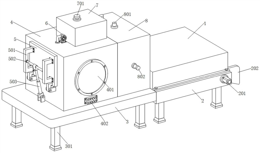
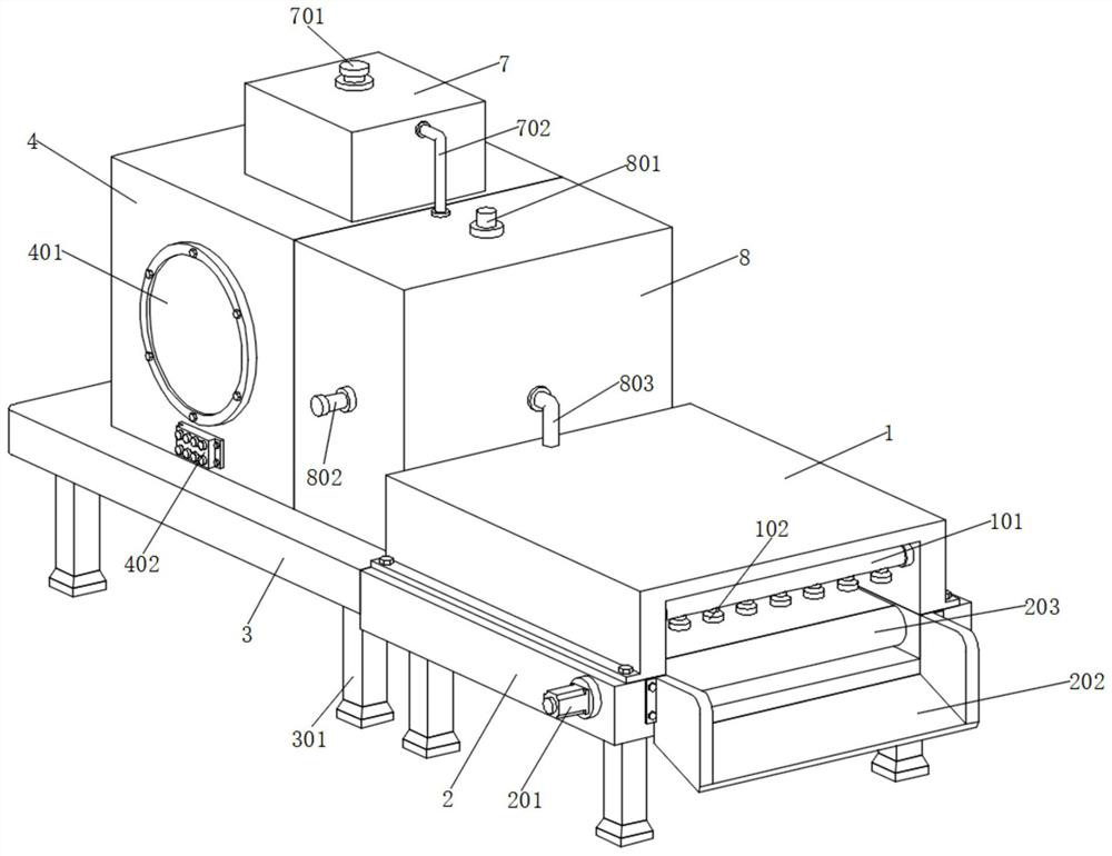
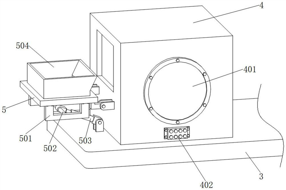
[0037] like Figure 1-8 As shown, a high-efficiency slag processing device for high-temperature slag waste heat recovery proposed by the present invention includes a conveying frame 2, a base 3 and a first processing box 4, and the base 3 and the bottom of the conveying frame 2 are fixed A support leg 301 is installed, and the base 3 and the conveyor 2 can be easily supported by the support leg 301. The top of the base 3 is fixedly installed with a first processing box 4, and one side of the first processing box 4 is movably installed with a sealing plate 5. An upper hopper 504 extending into the first processing box 4 is fixedly installed on one side of the sealing plate 5, a fixing frame 501 is fixedly installed on one side of the sealing plate 5, and a rotating shaft 502 is movably installed between the fixing frames 501, and the rotating shaft A first electric push rod 503 is movably installed between the 502 and the base 3, which can introduce the molten slag into the upp...

Embodiment 2

[0039] like Figure 1-8 As shown in the figure, a high-efficiency slag treatment device for high-temperature slag waste heat recovery proposed by the present invention, compared with the first embodiment, this embodiment also includes a fixed installation on the base 3 on one side of the first treatment box 4 There is a second treatment box 8. The inside of the second treatment box 8 is provided with a water storage chamber 804 and a heating chamber 807. The water storage chamber 804 is located on the top of the heating chamber 807. A second water injection port 801 corresponding to the water storage chamber 804 is fixedly installed on the top of the second treatment tank 8, and water can be easily introduced into the water storage chamber 804 for storage through the second water injection port 801. The bottom of the heating chamber 807 is movably installed. There is a pushing frame 808 corresponding to the vibration frame 10, and the vibration of the vibration frame 10 can be...


PUM


Abstract

The efficient slag treatment device comprises a conveying frame, a base and a first treatment box, the first treatment box is fixedly mounted at the top of the base, and a sealing plate is movably mounted on one side of the first treatment box; and a feeding hopper extending into the first treatment box is fixedly installed on one side of the sealing plate, a supporting frame is fixedly installed at the bottom of the interior of the first treatment box, and a vibration base is movably installed at the top of the supporting frame. Through mutual cooperation of a sealing plate, a feeding hopper and a vibration frame, heat on molten slag can be conveniently and rapidly dissipated, the waste heat recovery efficiency is improved, through mutual cooperation of an evaporation box, an evaporation chamber, an air suction pipe and a second treatment box, water in the evaporation chamber can be heated and evaporated, and the waste heat recovery efficiency is improved. And air in the air suction pipe can be continuously heated through the heat absorption disc, waste heat can be conveniently and fully utilized, and convenience is improved.

Description

technical field [0001] The invention relates to the technical field of high-temperature slag treatment, in particular to a high-efficiency slag treatment device used for high-temperature slag waste heat recovery. Background technique [0002] Slag refers to the vitreous non-metallic material coated on the surface of molten metal after iron ore is smelted, so as to separate it from the main metal. During steelmaking, the slag-forming flux added is fused with the oxidation products of impurity elements in the raw material. Slag is formed into slag. The converter steelmaking process is carried out in a molten reaction medium. Slag is the product of the fire steelmaking process, which is mainly composed of oxides in metallurgical raw materials or oxides generated in the metallurgical process. After the steel smelting is completed, due to the smelting temperature as high as several thousand degrees, the resulting molten slag will also bring out a lot of heat. Since the molten sla...

Claims


Application Information

Patent Timeline
IPC IPC(8): C21B3/06C21B3/08
CPCC21B3/06C21B3/08C21B2400/024C21B2400/08Y02P10/25
Inventor 陆建宁陆睿郑璇曹刚川王圣冬
Owner NANJING HUADIAN ENERGY SAVING & ENVIRONMENTAL PROTECTION EQUIP
Why Eureka
Try Eureka