Anti-curing oil storage tank for oil field and using method

A technology for oil storage tanks and oil fields, which is applied to tank trucks, sustainable packaging, containers, etc. It can solve the problems of surrounding environmental pollution, increase costs, and affect single well production, and achieve good fluidity

Active Publication Date: 2022-07-08
山东石油化工学院
View PDF11 Cites 0 Cited by
  • Summary
  • Abstract
  • Description
  • Claims
  • Application Information

AI Technical Summary

Problems solved by technology

At present, most of the treatment methods in oil fields are to directly replace the oil storage tanks, which not only affects the production of a single well, increases the cost, but also brings pollution to the surrounding environment

Method used


Image

  • Anti-curing oil storage tank for oil field and using method
  • Anti-curing oil storage tank for oil field and using method
  • Anti-curing oil storage tank for oil field and using method

Examples


Embodiment 1

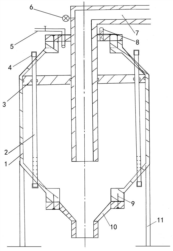
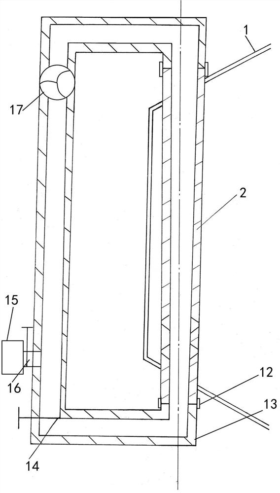
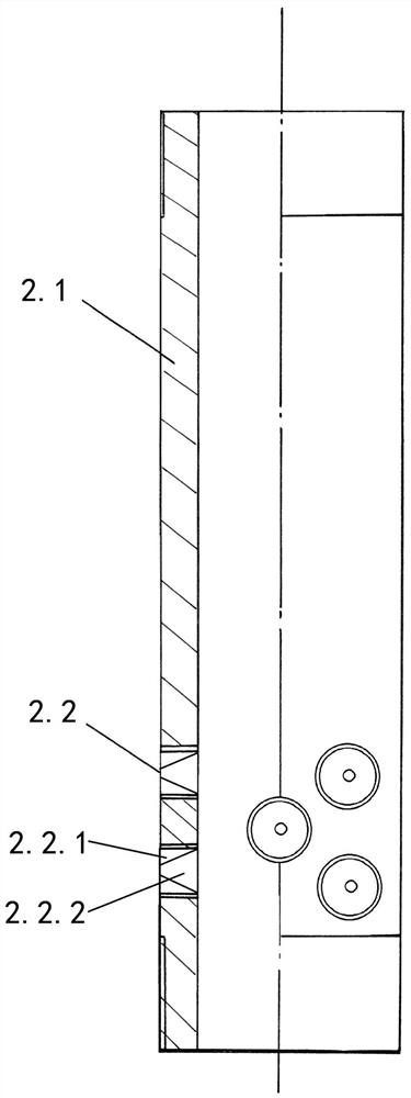
[0034] Example 1, refer to Figure 1-4, An oilfield anti-solidification oil storage tank mentioned in the present invention includes a tank body 1, a liquid discharge pressure plate 3, a compressed gas inlet and outlet pipe 5, a pressure gauge 6, a liquid inlet pipe 7, a safety valve 8, a connecting bolt 9, The liquid discharge pipe 10, the bracket 11, the tank body 1 is installed and fixed by the lower bracket 11, the upper end of the tank body 1 is provided with a liquid inlet pipe 7 and a compressed gas inlet and outlet pipe 5, and the lower end is fixed by a connecting bolt 9 with a discharge pipe. The liquid pipe 10 is provided with a liquid discharge pressure plate 3 in the inner cavity of the tank body 1, and the lower end outlet of the liquid inlet pipe 7 is located in the lower part of the inner cavity of the tank body 1, which also includes a permeation dilution pipe 2, a sealing blind plug 4, The external connection head 12, the oil return pipe 13, the pressure hold...

Embodiment 2

[0044] Embodiment 2, a kind of oilfield anti-solidification oil storage tank mentioned in the present invention, its technical scheme is: comprise tank body 1, liquid discharge pressure plate 3, compressed gas inlet and outlet pipes 5, liquid inlet pipes 7, connecting bolts 9, The liquid discharge pipe 10, the bracket 11, the tank body 1 is installed and fixed by the lower bracket 11, the upper end of the tank body 1 is provided with a liquid inlet pipe 7 and a compressed gas inlet and outlet pipe 5, and the lower end is fixed by a connecting bolt 9 with a discharge pipe. The liquid pipe 10 is provided with a liquid discharge pressure plate 3 in the inner cavity of the tank body 1, and the lower end outlet of the liquid inlet pipe 7 is located in the lower part of the inner cavity of the tank body 1, which also includes a permeation dilution pipe 2, a sealing blind plug 4, The external connection head 12, the oil return pipe 13, the pressure holding valve 14, the external fuel ...


PUM


Abstract

The invention relates to the technical field of oil storage tanks for the petroleum industry, in particular to an oil field anti-solidification oil storage tank and a using method. According to the technical scheme, a plurality of permeation dilution pipes are arranged and installed in an inner cavity of a tank body, the middle of each permeation dilution pipe penetrates through a liquid discharging pressurization plate, the upper end and the lower end of each permeation dilution pipe penetrate through the outer wall of the tank body to extend out of the tank body, the permeation dilution pipes can be connected with an oil return pipe through external connectors, and a circulating pump and a pressure building valve are installed on the oil return pipe; and the external oil distribution tank is connected to an oil return pipe through a circulating valve. The anti-solidification oil storage tank has the beneficial effects that dissolved liquid flows to the inner cavity of the tank body through the osmotic pressure difference device of the osmotic dilution pipe by pressing of the circulating pump, active diffusion under positive pressure is realized, and the purpose of diluting and dissolving solidified oil liquid in the tank body is achieved, so that the anti-solidification function of the oil storage tank is realized, the service life of the oil storage tank is prolonged, and influence on production of a single well is avoided; the use cost is reduced, and the pollution to the surrounding environment is also reduced.

Description

technical field [0001] The invention relates to the technical field of an oil storage tank for the petroleum industry, in particular to an oil field anti-solidification oil storage tank and a method of using the same. Background technique [0002] In the process of oil exploitation, there is a large number of single-well production. The so-called single-well production is due to geological reasons, resulting in small oil reservoir blocks and relatively isolated production wells. Therefore, the produced crude oil cannot be incorporated into large In addition, some exploration wells in new blocks are also using single-well production due to the limitation of conditions. The characteristic of single-well production is that the produced oil needs to be temporarily stored in oil storage tanks. Then, the oil tanker is used to transport the oil to maintain the balance between the oil in the oil storage tank and the transportation, so as to achieve the purpose of continuous producti...

Claims


Application Information

Patent Timeline
IPC IPC(8): B65D88/54B65D88/74
CPCB65D88/548B65D88/745Y02W30/80
Inventor 刘坤董龙飞张昕梁月王田田
Owner 山东石油化工学院
Why Eureka
Try Eureka