Exhaust blow-drying device

The technology of a casing and a vacuum cleaner is applied in the field of cleaning robots, which can solve the problems of inconvenient and fast drying of mops, and achieve the effect of improving the connection strength.

Pending Publication Date: 2022-07-12
麦岩智能科技(北京)有限公司
View PDF0 Cites 0 Cited by
  • Summary
  • Abstract
  • Description
  • Claims
  • Application Information

AI Technical Summary

Problems solved by technology

[0004] The purpose of the present invention is to solve the disadvantages of the prior art that it is inconvenient to quickly dry the mop, and propose an exhaust drying device

Method used


Image

  • Exhaust blow-drying device
  • Exhaust blow-drying device
  • Exhaust blow-drying device

Examples


Embodiment 1

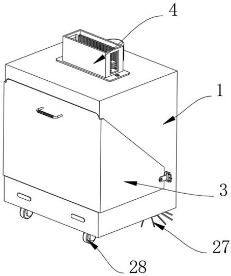
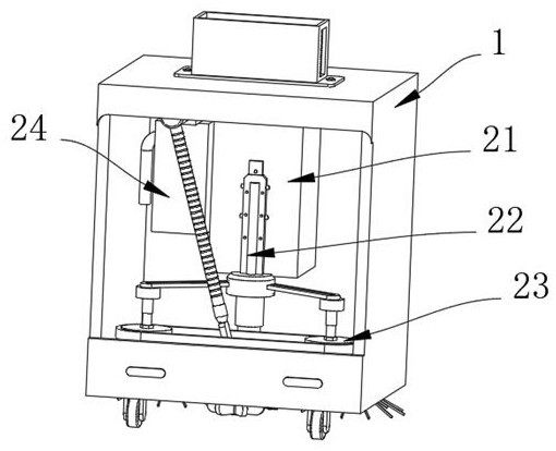
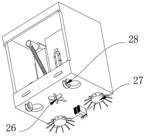
[0041] Example 1, as Figure 1-9 As shown, the present invention provides an exhaust drying device, comprising a casing 1 and a cleaning structure 2, the interior of the casing 1 is provided with a cleaning structure 2 for drying the mop, and the cleaning structure includes a cleaning structure for driving the mop head 23 to move The driver 22, the case 21 for regulating the driver 22, the vacuum box 24 for inhaling the sweeping dust, the connecting component 25 for connecting the vacuum box 24 and blowing the air in the vacuum box 24 to the tractor 23, With the sweeping head 26 of the cleaning tractor 23, the cleaning element 27 for cleaning the ground and the cleaning component 29 for cleaning the sweeping head 26 in time, one end of the casing 1 is provided with a limit structure 3, and the upper surface of the casing 1 is provided with a limit structure 3. A counterweight structure 4 is provided.

[0042] The specific settings and functions of the cleaning structure 2 , t...

Embodiment 2

[0047]Embodiment 2, on the basis of embodiment 1, as Figure 8 and Figure 9 As shown, the counterweight structure 4 includes a backing plate 41. The backing plate 41 is fixedly connected to the upper surface of the casing 1 by means of bolts. Hole 43, frame 42 A plurality of tooth blocks 44 are fixedly connected to one side of the inner wall of the rectangular hole 43, and the plurality of tooth blocks 44 are evenly distributed on one side of the inner wall of the rectangular hole 43. A counterweight 45 is used to increase the gravity of the casing 1 and improve the cleaning strength of the ground, so that the number of counterweights 45 can be increased or decreased according to the actual cleaning needs, thereby increasing the pressure of the casing 1 on the ground, and then Adjust the effect of the cleaning strength of the tractor 23 on the ground. One side of the frame 42 is slidably inserted with a pull rod 46, the two arms of the pull rod 46 are fixedly connected with...


PUM


Abstract

The invention provides an exhausting and blow-drying device, and relates to the technical field of cleaning robots, the exhausting and blow-drying device comprises a machine shell and a cleaning structure, and the cleaning structure used for blow-drying mop cloth is arranged in the machine shell; the cleaning structure comprises a driver used for driving the mopping head to move, a machine box used for adjusting and controlling the driver, a dust suction box used for sucking sweeping dust, a connecting assembly used for being connected with the dust suction box and blowing air in the dust suction box to the mopping head, and a sweeping head used for cleaning the mopping head. The sweeping piece is used for sweeping the ground, the cleaning assembly is used for cleaning sweeping heads in time, a driver is installed on the inner wall of the machine shell, the output end of the driver is fixedly connected with two mopping heads, two preformed holes are formed in the lower surface of the machine shell, the size of the preformed holes is matched with the size of the mopping heads, and the mopping heads can stretch out of the preformed holes. One side of the machine box is fixedly connected with a dust suction box, and one side of the dust suction box communicates with an air outlet used for exhausting of the dust suction box. By means of the mop drying device, the problem that the mop is inconvenient to blow-dry rapidly is solved.

Description

technical field [0001] The invention relates to the technical field of cleaning robots, in particular to an exhaust air drying device. Background technique [0002] Cleaning robots refer to small mechanical equipment used to clean the ground. With the development of intelligence, smart home applications have gradually become more extensive. Cleaning robots mainly integrate three functions: sweeping, vacuuming, mopping, and mopping. Divided into wet mopping and dust pushing. The cleaning robot with wet mopping function itself does not have the function of drying the mop. When the mop needs to be cleaned and dried, the robot needs to return to the supporting base station and use the related functions of the base station to clean and dry the mop. [0003] The cleaning robot mainly has functions such as sweeping, vacuuming, mopping, etc., and needs to be equipped with a full-featured base station to work together. After the robot has been working for a period of time, when the...

Claims


Application Information

Patent Timeline
Patent Type & Authority Applications(China)
IPC IPC(8): A47L11/24A47L11/28A47L11/40
CPCA47L11/24A47L11/28A47L11/40A47L11/4013A47L11/4094
Inventor 李宇浩齐洪明
Owner 麦岩智能科技(北京)有限公司
Why Eureka
Try Eureka