Stamping die for metal plate stamping

A stamping die and sheet metal technology, applied in the direction of manufacturing tools, metal processing equipment, feeding devices, etc., can solve the problems of increasing the risk factor of the staff and increasing the workload of the staff, so as to reduce the probability of adhesion and improve The rate of fall, the effect of reducing workload

Pending Publication Date: 2022-07-12
南通旭志精工科技有限公司
View PDF1 Cites 0 Cited by
  • Summary
  • Abstract
  • Description
  • Claims
  • Application Information

AI Technical Summary

Problems solved by technology

[0004] When the stamping die punches sheet metal parts, a large amount of waste will be generated. The waste will fall into the gap between the die and the punch through the discharge hole at the bottom of the die, and then the staff will use tools to push the waste out, which will not only increase the The workload of the staff is increased, and the staff is required to be close to the punch press, which increases the risk factor of the staff when working

Method used


Image

  • Stamping die for metal plate stamping
  • Stamping die for metal plate stamping
  • Stamping die for metal plate stamping

Examples


Embodiment 1

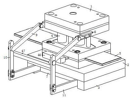
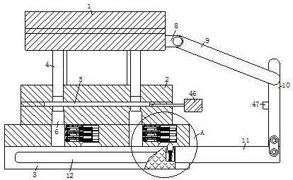
[0031] like Figure 1 to Figure 2 As shown, a stamping die for sheet metal stamping according to an embodiment of the present invention includes an upper die 1, a lower die 2, a support table 3 and a pusher assembly; a plurality of punches are installed on the bottom surface of the upper die 1 4. The metal sheet 5 is slidably mounted on the top groove of the lower mold 2, and a plurality of waste holes 6 are opened on the bottom surface of the top groove of the lower mold 2. The waste holes 6 penetrate through the lower mold 2, and the waste holes The inner wall of 6 is slidingly matched with the outer wall of the punch 4, the bottom surfaces of both sides of the lower die 2 are fixedly connected to the support table 3, and one side of the lower die 2 is installed with a pusher assembly; the pusher assembly includes a push plate 7 and transmission unit, a push plate 7 is slidably installed between the support platforms 3 on both sides, the top surface of the push plate 7 is sl...

Embodiment 2

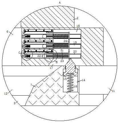
[0041] like Figure 8 As shown in the comparison example 1, another embodiment of the present invention is that: the oblique angle of the push knife 44 is provided with a plurality of turning grooves 48, the inside of the turning groove 48 is rotated to install the turning plate 49, and the turning The bottom surface of the plate 49 is fixed to a plurality of No. 6 springs 50, and the bottom end of the No. 6 springs 50 is fixed to the inner wall of the turning slot 48. The cross section of the turning plate 49 is semi-conical, and the The bottom end coincides with the bottom end of the rotating groove 48, and the top of the rotating plate 49 is located outside the rotating groove 48, and the rotating shaft of the rotating plate 49 is located on the top of the rotating plate 49 close to the side of the rotating groove 48; when in use, push the knife When 44 is inserted into the bottom of the metal sheet 5, the metal sheet 5 slides up along the oblique angle of the pusher 44, an...


PUM


Abstract

The invention belongs to the field of stamping dies, and particularly relates to a stamping die for sheet metal stamping, which comprises an upper die, a lower die, a support table and a pushing component. A plurality of punches are installed on the bottom face of the upper die, a metal sheet is slidably installed in a groove in the top face of the lower die, a plurality of waste holes are formed in the bottom face of the groove in the top face of the lower die, supporting tables are fixedly connected to the bottom faces of the two sides of the lower die, a push plate is slidably installed between the supporting tables on the two sides, and a transmission unit is installed on one side of the push plate. The top end of the transmission unit is fixedly connected with the side surface of the upper die; the upper die and the lower die are pushed by a punching machine to be closed, the punch is driven to punch a metal sheet, waste falls down from the waste hole, the upper die descends to conduct power transmission through the transmission unit, the push plate is pushed to slide between the supporting tables on the two sides, the falling waste is pushed out, the waste accumulation probability is reduced, the workload of workers is reduced, and the production efficiency is improved. And the safety of workers during working is improved.

Description

technical field [0001] The invention belongs to the field of stamping dies, in particular to a stamping die for sheet metal stamping. Background technique [0002] Sheet metal stamping is a stamping and forming process for metal sheets. During the sheet metal stamping process, stamping dies are used to stamp and cut the metal sheet, and the excess scrap of the sheet metal parts is punched and cut, and the sheet metal parts are punched and cut at the same time. Forming, and finally stamping into qualified sheet metal parts. [0003] A Chinese patent with publication number CN113059060A discloses an automobile sheet metal stamping die, including an upper die, a lower die and a pressing plate; the top surface of the lower die is provided with a die groove; the interior of the die groove is provided with a sheet metal The edge of the sheet metal part is designed with a 90-degree bending structure; the upper part of the sheet metal part is provided with a connecting plate; the b...

Claims


Application Information

Patent Timeline
IPC IPC(8): B21D28/14B21D43/20B21D45/02
CPCB21D28/14B21D43/20B21D45/02Y02P70/10
Inventor 胡志彪文明方丽娟
Owner 南通旭志精工科技有限公司
Why Eureka
Try Eureka