Corrugated pipe manufacturing system and method

A corrugated pipe and plate technology, applied in the field of corrugated pipes, can solve the problems of high production cost

Active Publication Date: 2022-07-12
SHENYANG AEROSUN FUTAI EXPANSION JOINT
View PDF8 Cites 0 Cited by
  • Summary
  • Abstract
  • Description
  • Claims
  • Application Information

AI Technical Summary

Problems solved by technology

[0004] However, the current bellows are manufactured throu...

Method used


Image

  • Corrugated pipe manufacturing system and method
  • Corrugated pipe manufacturing system and method
  • Corrugated pipe manufacturing system and method

Examples


Embodiment Construction

[0036] Exemplary embodiments of the present application will be described in more detail below with reference to the accompanying drawings. While exemplary embodiments of the present application are shown in the drawings, it should be understood that the present application may be embodied in various forms and should not be limited by the embodiments set forth herein. Rather, these embodiments are provided so that the application will be more thoroughly understood, and will fully convey the scope of the application to those skilled in the art.

[0037] It should be noted that, unless otherwise specified, the technical or scientific terms used in this application should have the usual meanings understood by those skilled in the art to which this application belongs.

[0038] first

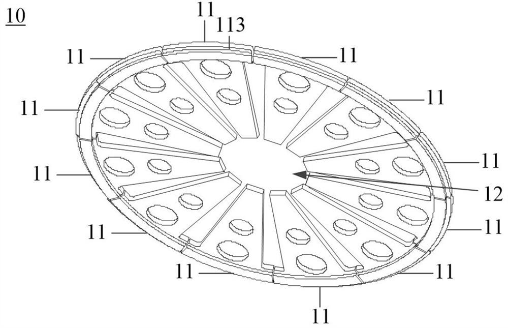
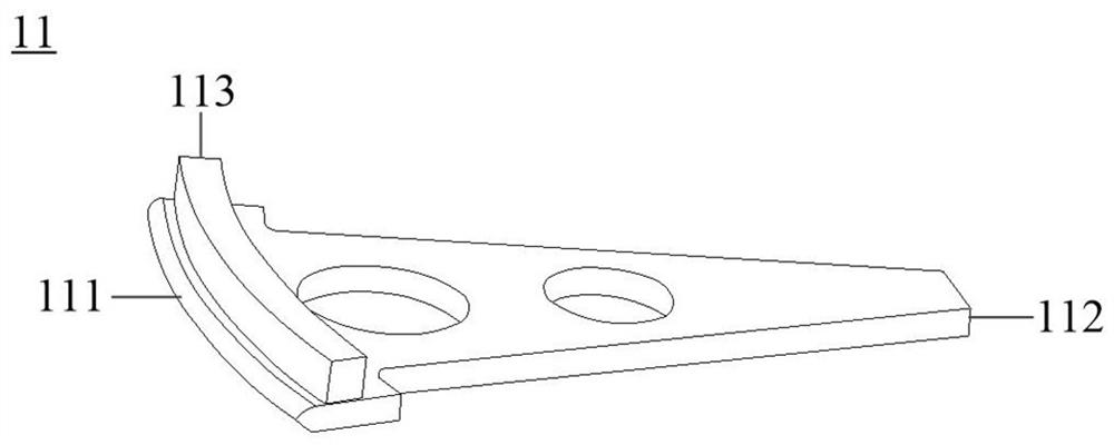
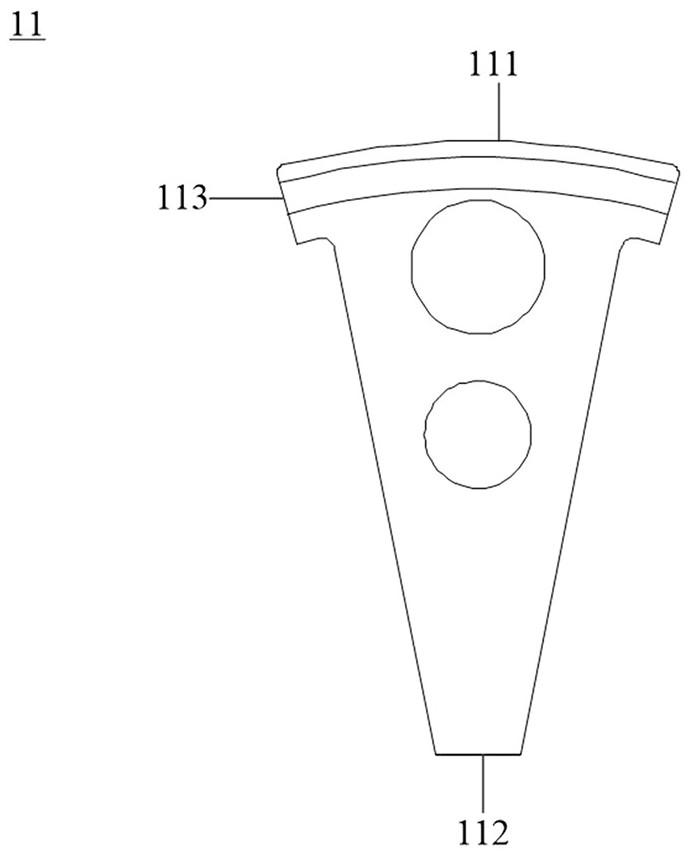
[0039] The embodiment of the present application provides a corrugated tube manufacturing system, see Figure 1 to Figure 12 As shown, the bellows manufacturing system includes: a first device 10 ...


PUM


Abstract

The invention provides a corrugated pipe manufacturing system and method, the corrugated pipe manufacturing system comprises a first device, a second device and a third device, the first device adopts an expansion forming technology to conduct primary shaping on the first position of a plate, and after primary shaping, the first position of the plate is subjected to secondary shaping; a first arc-shaped convex part which is convex towards a first surface far away from the plate is formed at a first position of the plate; the second equipment adopts the rolling forming technology to conduct secondary shaping on the first position of the plate, after secondary shaping, a first arc-shaped concave part protruding towards the second surface away from the plate and a second arc-shaped convex part protruding towards the first surface are formed in the first position of the plate, and the second arc-shaped convex part is further shaped for the first arc-shaped convex part; the second surface of the plate is opposite to the first surface of the plate; and the third equipment shears the second position of the plate through the rolling shearing technology, and the first position and the second position of the plate correspond to the two axial ends of the corrugated pipe correspondingly.

Description

technical field [0001] The present application relates to the technical field of corrugated pipes, and in particular, to a corrugated pipe manufacturing system and method. Background technique [0002] The gas turbine exhaust diffuser is connected between the gas turbine and the waste heat boiler. The gas turbine exhaust diffuser can expand and depressurize the high-temperature helical exhaust gas discharged from the gas turbine, and the gas turbine exhaust diffuser can divert the expanded and depressurized gas into a turbulent gas with certain rules, while the gas turbine exhaust gas The turbulent gas diverted by the gas diffuser can enter the inlet flue of the waste heat boiler for absorption by the waste heat boiler. Since the gas entering the waste heat boiler is a turbulent gas, the heating surfaces of the waste heat boiler can be uniform, so that the heat absorption efficiency of the waste heat boiler can be improved, and the operation safety of the waste heat boiler ...

Claims


Application Information

Patent Timeline
IPC IPC(8): B23P23/04B23P15/00B21D13/04B23Q1/00
CPCB23P23/04B23P15/00B21D13/04B23Q1/0009Y02T10/12
Inventor 周桐李亮吴来昊孙丹邵长乐杨丙旭
Owner SHENYANG AEROSUN FUTAI EXPANSION JOINT
Why Eureka
Try Eureka