Combined box girder structure and construction method thereof

A beam structure and combination box technology, applied in bridges, bridge construction, bridge materials, etc., can solve the problems of cumbersome internal formwork erection and dismantling processes, low effective bearing capacity, limited spanning capacity, etc., and achieve rapid assembly construction. , The effect of reducing the weight of the structure and increasing the spanning capacity

Pending Publication Date: 2022-07-12
HUNAN UNIV
View PDF7 Cites 0 Cited by
  • Summary
  • Abstract
  • Description
  • Claims
  • Application Information

AI Technical Summary

Problems solved by technology

[0004] The invention provides a combined box girder structure and its construction method, which are used to solve the technical problems of low effective bearing capacity of the box girder structure in current bridge engineering, cumbersome erection and dismantling process of internal formwork, and limited spanning capacity

Method used


Image

  • Combined box girder structure and construction method thereof
  • Combined box girder structure and construction method thereof
  • Combined box girder structure and construction method thereof

Examples


Embodiment 1

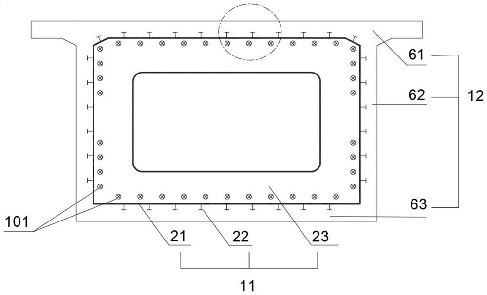
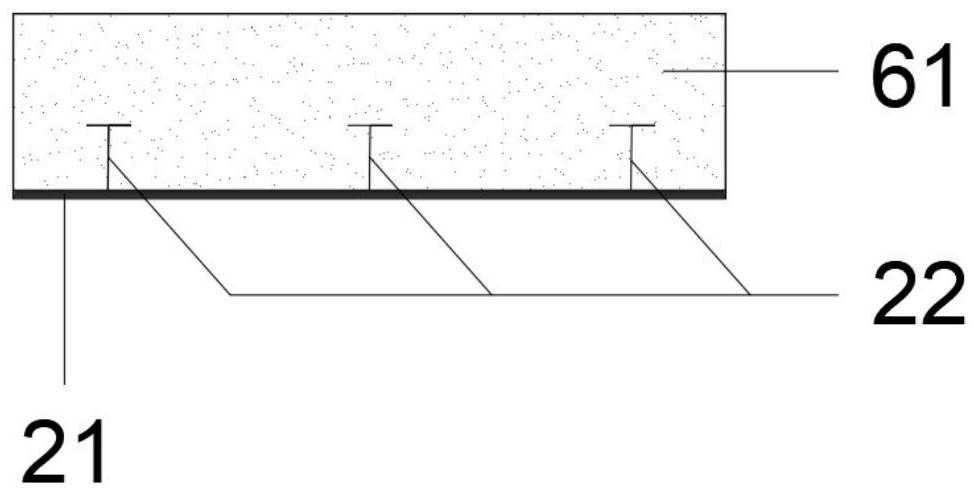
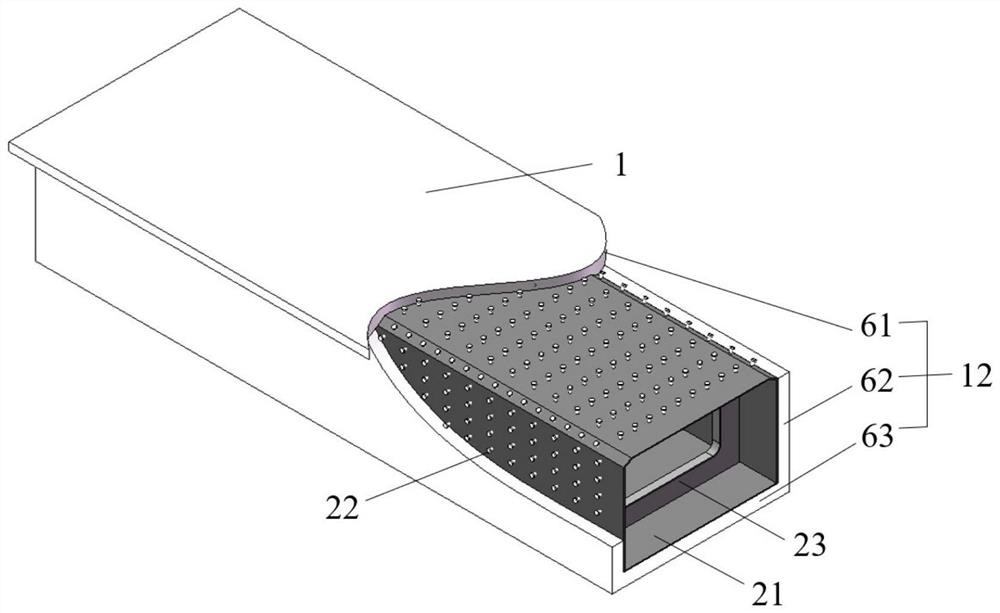
[0049] like Figure 1-Figure 5 As shown, the composite box girder structure 1 of this embodiment includes a box-shaped outer shell 12 and an inner core 11 . The inner core 11 includes a thin-walled steel shell 21 , a diaphragm 23 and a shear connector 22 , and the diaphragm 23 runs along the inner core 11 . The cross-sectional direction of the thin-walled steel shell 21 is fixed on the inner side of the thin-walled steel shell 21 , and the thin-walled steel shell 21 is fitted and fixed on the inside of the box-shaped shell 12 through the shear force connector 22 .

[0050] The thin-walled steel shell 21 is a box structure with a "mouth"-shaped cross-section, which is completely covered and fixed on the inner surface of the box-shaped shell 12; m.

[0051] The diaphragm 23 is a T-shaped steel plate, and there are a plurality of them along the longitudinal bridge direction, with a distance of 2m to 10m and a thickness of 0.008m to 0.015m. The diaphragm 23 is provided with exter...

Embodiment 2

[0062] like Figure 6-Figure 9 As shown, the composite box girder structure 1 of this embodiment includes a box-shaped outer shell 12 and an inner core 11 . The inner core 11 includes a thin-walled steel shell 21 , a diaphragm 23 and a shear connector 22 , and the diaphragm 23 runs along the inner core 11 . The cross-sectional direction of the thin-walled steel shell 21 is fixed on the inner side of the thin-walled steel shell 21 , and the thin-walled steel shell 21 is fitted and fixed on the inside of the box-shaped shell 12 through the shear force connector 22 .

[0063] The thin-walled steel shell 21 is a box structure with a "mouth"-shaped cross-section, which is completely covered and fixed on the inner surface of the box-shaped shell 12; m.

[0064] The diaphragm 23 is a T-shaped steel plate, and there are a plurality of them along the longitudinal bridge direction, with a distance of 2m to 10m and a thickness of 0.008m to 0.020m. The diaphragm 23 is provided with exter...

Embodiment 3

[0070] like Figure 10 and Figure 11 As shown, the composite box girder structure 1 of this embodiment includes a box-shaped outer shell 12 and an inner core 11 . The inner core 11 includes a thin-walled steel shell 21 , a diaphragm 23 and a shear connector 22 , and the diaphragm 23 runs along the inner core 11 . The cross-sectional direction of the thin-walled steel shell 21 is fixed on the inner side of the thin-walled steel shell 21 , and the thin-walled steel shell 21 is fitted and fixed on the inside of the box-shaped shell 12 through the shear force connector 22 .

[0071] The thin-walled steel shell 21 has a "冂"-shaped structure in cross section, which is completely covered and fixed on the inner surface of the UHPC bridge deck 61 and the UHPC web 62; the thin-walled steel shell 21 is made of weathering steel, and the thickness of the thin-walled steel shell 21 is 0.008m ~0.015m.

[0072] The diaphragm 23 is a T-shaped steel plate, and there are a plurality of them a...


PUM


Abstract

The invention discloses a combined box girder structure and a construction method thereof, the combined box girder structure comprises a box-shaped shell and an inner core, the inner core comprises a thin-wall steel shell, a shearing force connecting piece and a transverse partition plate, and the thin-wall steel shell is fixedly attached to the interior of the box-shaped shell through the shearing force connecting piece. The inner core and the box-shaped shell of the combined box girder structure are jointly stressed, the thickness of a plate can be further reduced, the self weight of the structure is reduced, the effectiveness of the structure for resisting use loads is improved, the spanning capacity of a box girder bridge is improved, the inner core is directly used as an internal formwork of the box-shaped shell, rapid construction of bridge construction is achieved, and the construction cost is reduced. The defects of conventional pouring are avoided, the problems of overlarge transverse local stress, overall stability, section distortion, web shear bearing capacity and the like can be solved, and good durability and wide application prospects are achieved.

Description

technical field [0001] The invention relates to the technical field of bridge engineering, in particular to a combined box girder structure made of an inner core and a box-shaped outer shell and a construction method thereof. Background technique [0002] Prestressed concrete box girder bridges have the advantages of fast construction and good economic performance, and have been widely used all over the world. However, with the continuous increase of the bridge span, the prestressed concrete box girder bridge faces technical problems such as the deflection of the main span, the cracking of the beam body, and the excessive self-weight. Traditional concrete has a heavy weight and low strength, and the risk of beam cracking is high under load. Most of the structural bearing capacity is used to overcome the dead weight of the bridge structure. Therefore, the span of conventional prestressed concrete box girder bridges is difficult to exceed 300m. Due to the large shrinkage and ...

Claims


Application Information

Patent Timeline
Patent Type & Authority Applications(China)
IPC IPC(8): E01D2/04E01D21/00E01D101/28
CPCE01D2/04E01D21/00E01D2101/285
Inventor 邵旭东李盼盼曹君辉
Owner HUNAN UNIV
Why Eureka
Try Eureka