
Eureka
For R&D, Eureka makes reading and utilizing patents & technical documents easy.
Eureka AIR
Designed for self-driven R&D workflows. Generate viable solutions, solve complex R&D challenges, empower your innovation with AI.

Eureka Materials
Designed for material experts only. Revolutionize your material R&D, from search, analyze, to developing new materials.

TechResearch
Generate reliable direction feasibility study reports for your R&D in just a few steps.

TechSeek
Discover and master advanced knowledge NOW. Basics, ideas, possibilities, all at once.

TechMind
As an expert in R&D Theories, TechMind can generates customized viable solutions instantly.

TechRisk
Analyze your overall solution with one click, know your potential R&D risks in advance.

TechMonitor
Get weekly tech updates, stay abreast of the latest tech innovations and key insights.
Sewage purification treatment device for aquatic environment engineering and mounting method
A technology of sewage purification and treatment device, applied in water conservancy projects, water conservancy engineering equipment, sustainable biological treatment and other directions, can solve the problems of turbid water quality and odor, treating symptoms but not the root cause, and blockage of branch rivers, etc., and achieves the effect of improving water quality.
- Summary
- Abstract
- Description
- Claims
- Application Information
AI Technical Summary
Problems solved by technology
Method used
Image

Examples
Embodiment 1
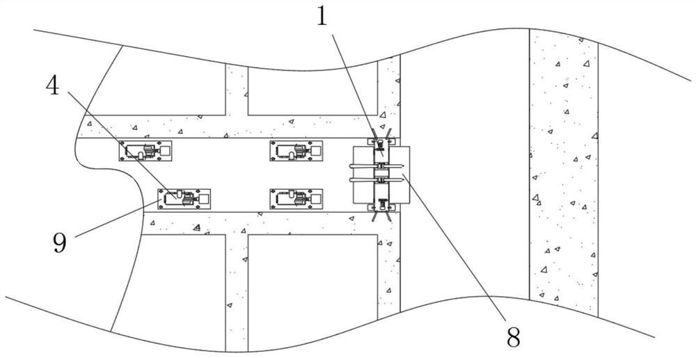
[0041] see figure 1 , figure 2 and Figure 5 , The sewage purification and treatment device for aquatic environment engineering of the present invention includes a water retaining component, which includes a water retaining dam 1 and a water level drop detection unit 7 installed on the retaining dam 1, and the water retaining component is installed at the junction of the T-shaped channel, Adjustment assembly 9, which is arranged at the water outlet of the pond, power generation assembly, which includes two groups of first power generation units 8 installed on the water retaining assembly and second power generation units 4 installed on the adjustment assembly 9, the water retaining dam 1 A guide hole 2 is opened laterally on the side of the guide hole 2, and an installation groove 3 is formed in the center of the bottom of the inner wall of the guide hole 2. The bottom of the inner wall of the installation groove 3 is fixed vertically upward with an electric telescopic rod 1...
Embodiment 2
[0044] see figure Image 6 and Figure 7 The adjustment assembly 9 includes a mounting plate 92 and a mounting rod 91. The four corners of the mounting plate 92 are provided with through holes 93 for the mounting rod 91 to pass through. The surface of the mounting rod 91 is provided with mounting holes 94 from top to bottom. The bottom of the inner wall of 94 is hinged with two triangular support plates 95 for supporting the mounting plate 92 through hinges.
[0045] The height of the mounting plate 92 on the mounting rod 91 can be adjusted to fit the uplifted or concave slopes of some branch rivers, and at the same time, it can prevent existing farmers from placing the drainage outlet on the river slope, and the soil on the river slope will appear. Occurs when it is lost under the scouring of water currents.
Embodiment 3
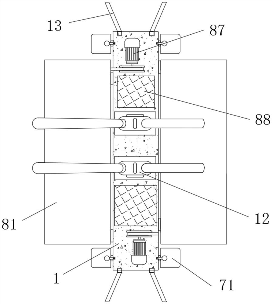
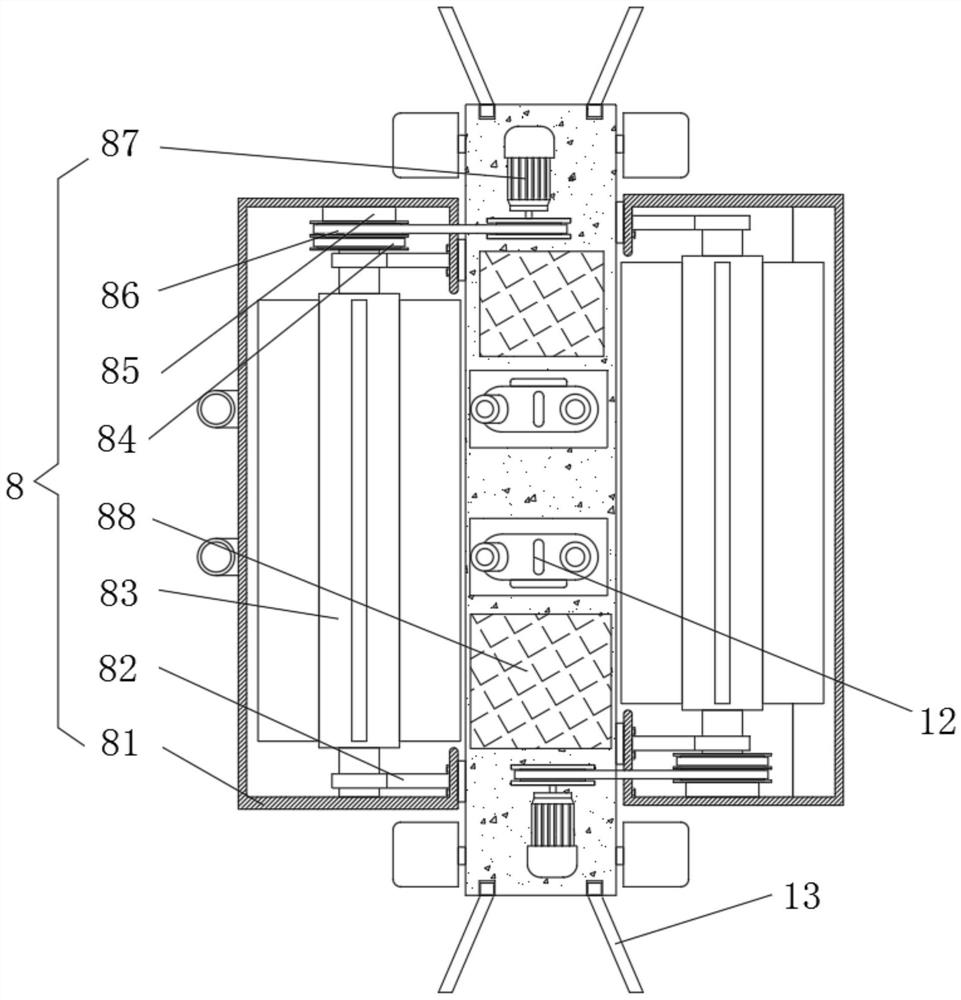
[0047] see figure 2 , image 3 , Figure 4 , the first power generation unit 8 includes a first battery 88, a first generator 87, a protective shell 81, and a drive plate 85 mounted on the inner wall of the protective shell 81. The inner wall of the protective shell 81 close to the inner side is fixedly connected with a mounting frame 82. The mounting frame The inner wall of 82 is plugged with the first generator drum 83 through the bearing, and the surface of the first generator drum 83 close to the end is connected to the transmission plate 85 through the first transmission belt 84, and the output shaft of the transmission plate 85 and the first generator 87 passes through the first transmission belt 84. The two transmission belts 86 are connected in a driving manner. The first generator drum 83 close to the main channel in the T-shaped channel is located above the diversion hole 2, and the first generator drum 83 close to the branch channel in the T-shaped channel is loca...
PUM
 Abstract
Description
Claims
Application Information
 - R&D Engineer
- R&D Manager
- IP Professional
- Industry Leading Data Capabilities
- Powerful AI technology
- Patent DNA Extraction
Browse by: Latest US Patents, China's latest patents, Technical Efficacy Thesaurus, Application Domain, Technology Topic, Popular Technical Reports.
© 2024 PatSnap. All rights reserved.Legal|Privacy policy|Modern Slavery Act Transparency Statement|Sitemap|About US| Contact US: help@patsnap.com