
Rope coring near-bit measurement while drilling system and method

A measurement-while-drilling technology near the drill bit, which is applied in drilling measurement, drilling automatic control system, measurement, etc. It can solve the problems of mud pulse signal identification, impact of measuring device life time, data distortion, etc., and achieve the goal of reducing drilling assistance. time, improve the power supply endurance, and the effect of strong data transmission capability

Active Publication Date: 2022-07-12
EXPLORATION TECH RES INST OF CHINESE ACADEMY OF GEOLOGICAL SCI
View PDF5 Cites 0 Cited by
  • Summary
  • Abstract
  • Description
  • Claims
  • Application Information

AI Technical Summary

Problems solved by technology

The existing wireline coring while drilling measurement device is installed on the inner pipe assembly, which is far away from the drill bit, generally about 6-7 meters, and some engineering parameters measured, such as drilling pressure, torque, vibration, etc., cannot accurately reflect the drill bit. Due to the actual working conditions, due to the narrow space of the drilling tool, the size and quantity of the battery are reduced accordingly, and the battery life of the measuring device will also be greatly affected. In addition, considering factors such as the small drilling fluid displacement and downhole noise interference, the mud pulse signal cannot be detected by the ground. Effective computer identification may cause data distortion or even loss

Method used


Image

  • Rope coring near-bit measurement while drilling system and method
  • Rope coring near-bit measurement while drilling system and method
  • Rope coring near-bit measurement while drilling system and method

Examples


Embodiment Construction

[0032] The technical solutions in the embodiments of the present invention will be clearly and completely described below with reference to the accompanying drawings in the embodiments of the present invention. Obviously, the described embodiments are only a part of the embodiments of the present invention, rather than all the embodiments. Based on the embodiments of the present invention, all other embodiments obtained by those of ordinary skill in the art without creative efforts shall fall within the protection scope of the present invention.

[0033] The purpose of the present invention is to provide a near-bit measurement system and method for wireline coring, so as to solve the problems existing in the prior art.

[0034] In order to make the above objects, features and advantages of the present invention more clearly understood, the present invention will be described in further detail below with reference to the accompanying drawings and specific embodiments.

[0035] ...


PUM


Abstract

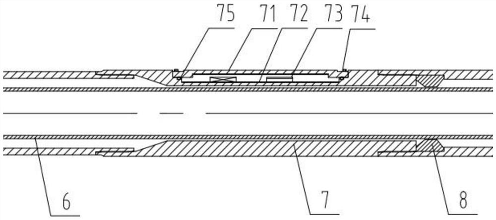
The invention discloses a rope coring near-bit measurement-while-drilling system and method, which can be used for measuring track parameters such as a vertex angle and an azimuth angle of a drill hole and near-bit engineering parameters such as bit pressure, torque, vibration and temperature, and a drill hole track parameter measuring short section and an engineering parameter measuring short section are respectively arranged at a fishing spearhead of an inner pipe assembly and a drill bit of an outer pipe assembly; in-hole near-bit data collected by the measuring short section is sent to the receiving short section arranged on the inner pipe assembly in a unified mode, the receiving short section receives and stores the data, meanwhile, data measured by a drilling track sensor in the receiving short section can be stored in real time, and after the inner pipe assembly is fished to the ground through a rock core full pipe, the inner pipe assembly is fished to the ground. And connecting a communication interface of the receiving short section with a computer, reading related data stored in the receiving short section by using written upper computer software, and emptying the data of the receiving short section. And the inner assembly is put again to carry out next-time coring drilling work, and the aim of measuring while drilling of the wire-line coring near-bit can be achieved by repeating the steps.

Description

technical field [0001] The invention relates to the technical field of geological exploration, in particular to a system and a method for measuring while drilling near the drill bit of wireline coring. Background technique [0002] As a relatively mature drilling method, wireline coring drilling is widely used in deep hole and even ultra-deep hole geological core drilling. Track data such as azimuth angle and relevant parameters such as WOB, torque, vibration, temperature, etc. near the drill bit, timely grasp the drilling trajectory and the actual working status of the drilling tools in the hole, and ensure the safety of the drilling process and drilling tools. Due to the small diameter of geological core drilling and the small displacement of drilling fluid, there are still many key technical problems of "jamming neck" in wireline core drilling to achieve near-bit WD measurement. [0003] In the field of oil drilling, the geosteering drilling technology characterized by n...

Claims


Application Information

Patent Timeline
Patent Type & Authority Applications(China)
IPC IPC(8): E21B25/00E21B44/00E21B44/04E21B45/00E21B47/022E21B47/07E21B47/13E21B47/26
CPCE21B25/00E21B47/13E21B47/26E21B47/022E21B44/00E21B44/04E21B45/00E21B47/07Y02A90/30
Inventor 韦海瑞李鑫淼朱芝同董巍贾炜刘广于好善袁明昕史兵言王兴无邵玉涛杨泽英伍朝辉张化民许万海张国庆
Owner EXPLORATION TECH RES INST OF CHINESE ACADEMY OF GEOLOGICAL SCI
Learn More