Dust collector motor

A vacuum cleaner and motor shaft technology, which is applied in the direction of vacuum cleaners, electric components, electromechanical devices, etc., can solve the problems of inconvenient disassembly, maintenance and cleaning of vacuum cleaner motors, and low heat dissipation efficiency, so as to facilitate daily maintenance and cleaning operations, improve efficiency, and facilitate The effect of daily cleaning

Pending Publication Date: 2022-07-12
余姚市驰力微电机有限公司
View PDF0 Cites 0 Cited by
  • Summary
  • Abstract
  • Description
  • Claims
  • Application Information

AI Technical Summary

Problems solved by technology

[0007] The present invention aims at the above-mentioned defects existing in the prior art, and proposes a vacuum cleaner motor, which solves the proble

Method used


Image

  • Dust collector motor
  • Dust collector motor
  • Dust collector motor

Examples


Embodiment 1

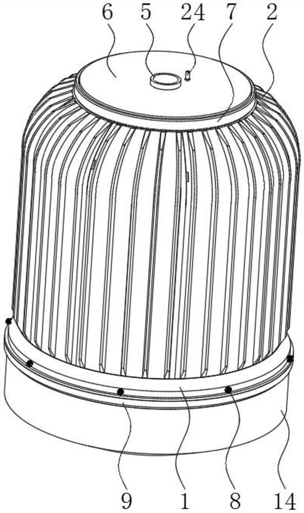
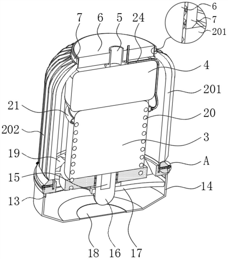
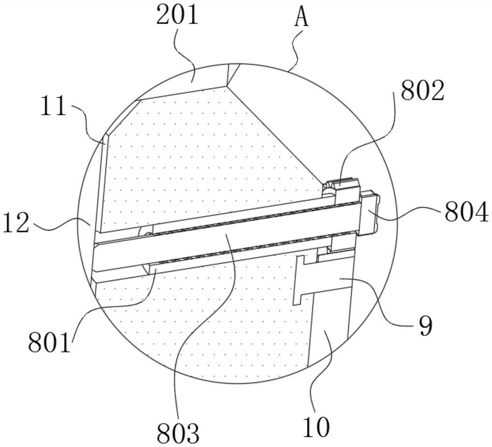
[0033] like Figure 1 to Figure 7 As shown, the vacuum cleaner motor in the embodiment of the present invention includes a base 1, the top of the base 1 is fixedly mounted with a motor shaft 3, and the top of the base 1 is movably connected with a number of housing components 2 located outside the motor shaft 3. A recovery box 4 is fixedly installed on the top, a sewage pipe 5 is fixedly connected to the top of the recovery box 4, a positioning plate 6 is fixedly sleeved on the outer surface of the sewage pipe 5, and a positioning sleeve 7 is threadedly sleeved on the outer surface of the positioning plate 6. The positioning sleeve The bottom of 7 is movably connected with the top of the housing assembly 2. The top of the base 1 is provided with a snap slot 11 at the bottom of the shell A number of locking mechanisms 8 are arranged on the sides. Due to the arrangement of the housing assembly 2 , it is convenient for the operator to disassemble the part, thereby facilitating th...

Embodiment 2

[0042] Compared with Embodiment 1, in this embodiment, the inside of the base 1 and the motor shaft 3 are screwed with a drain hole 20 , the bottom of the drain hole 20 penetrates through the base 1 and communicates with the interior of the protective cover 14 , and the sewage inlet groove 19 The top of the motor shaft 3 penetrates through the motor shaft 3 and is fixedly connected with a water conduit 21. The water conduit 21 is fixedly connected to the outer surface of the motor shaft 3. The provided water conduit 21 can facilitate the solenoid valve 22 and the connecting pipe 23 to perform simultaneous drainage of the plurality of drainage holes 20. Water is injected to make the distribution of water flow more uniform, and at the same time to ensure that the water flow quickly takes away more heat from the surface of the motor shaft 3; a solenoid valve 22 is fixedly connected to the right side of the water conduit 21, and a connecting pipe is fixedly connected to the right si...


PUM


Abstract

The invention belongs to the technical field of dust collector motors, and discloses a dust collector motor which comprises a base, a motor shaft is fixedly installed at the top of the base, a plurality of shell assemblies located on the outer side of the motor shaft are movably connected to the top of the base, and a recycling box is fixedly installed at the top of the motor shaft. And the top of the recycling box fixedly communicates with a blow-off pipe. By means of the threaded sleeve rod, the transmission gear shafts, the threaded rods and the tooth plates, after locking of the positioning sleeve to the tops of the shell assemblies is relieved, the multiple transmission gear shafts can be driven to rotate through the tooth plates by rotating the rotating sleeve, then locking of the multiple threaded rods to the clamping plates can be relieved at the same time, and locking of the multiple shell assemblies can be relieved at the same time; and by independently rotating any knob, the corresponding threaded rod can release the locking of the corresponding clamping plate under the limitation of the tooth plate on the transmission gear shaft and the threaded sleeve rod.

Description

technical field [0001] The invention relates to the technical field of vacuum cleaner motors, in particular to a vacuum cleaner motor. Background technique [0002] The motor is the heart of the vacuum cleaner. The vacuum cleaner motor mainly includes a dry vacuum cleaner motor and a dry and wet vacuum cleaner motor, and the vacuum cleaner motor is composed of a motor part and a fan part. [0003] At present, vacuum cleaner motors are different from ordinary mechanical motors in that they have more internal components and are relatively more complex. Although existing vacuum cleaner motors can also meet the needs of daily vacuuming, due to the complex internal structure of vacuum cleaner motors Although it improves the practicability of its functions, it also increases the frequency of its damage and failure due to more refined parts, so it is necessary to regularly disassemble its outer casing to facilitate the maintenance of internal parts, and the existing Most of the el...

Claims


Application Information

Patent Timeline
IPC IPC(8): H02K5/04H02K5/18H02K7/00H02K9/00B01D46/88B01D46/10A47L9/28A47L9/00
CPCH02K5/04H02K5/18H02K7/003H02K9/00B01D46/10A47L9/28A47L9/00
Inventor 兰军周永春陈金军
Owner 余姚市驰力微电机有限公司
Why Eureka
Try Eureka