Puncture device suitable for epidural space and epidural catheter placement in anesthesiology department

An epidural cavity and epidural technology, applied in the direction of puncture needles, trocars, etc., can solve the problems of poor stability and low working efficiency of epidural catheters, and achieve the effect of preventing bending

Inactive Publication Date: 2022-07-15
NANYANG SECOND GENERAL HOSPITAL
View PDF0 Cites 1 Cited by
  • Summary
  • Abstract
  • Description
  • Claims
  • Application Information

AI Technical Summary

Problems solved by technology

[0008] In order to solve the above-mentioned technical problems, the present invention provides a puncture device suitable for epidural space and epidural catheter placement in anesthesiology department, so as to solve the traditional epidural puncture and epidural catheter placement work efficiency proposed in the background technology. low, poor stability

Method used


Image

  • Puncture device suitable for epidural space and epidural catheter placement in anesthesiology department
  • Puncture device suitable for epidural space and epidural catheter placement in anesthesiology department
  • Puncture device suitable for epidural space and epidural catheter placement in anesthesiology department

Examples


Embodiment 1

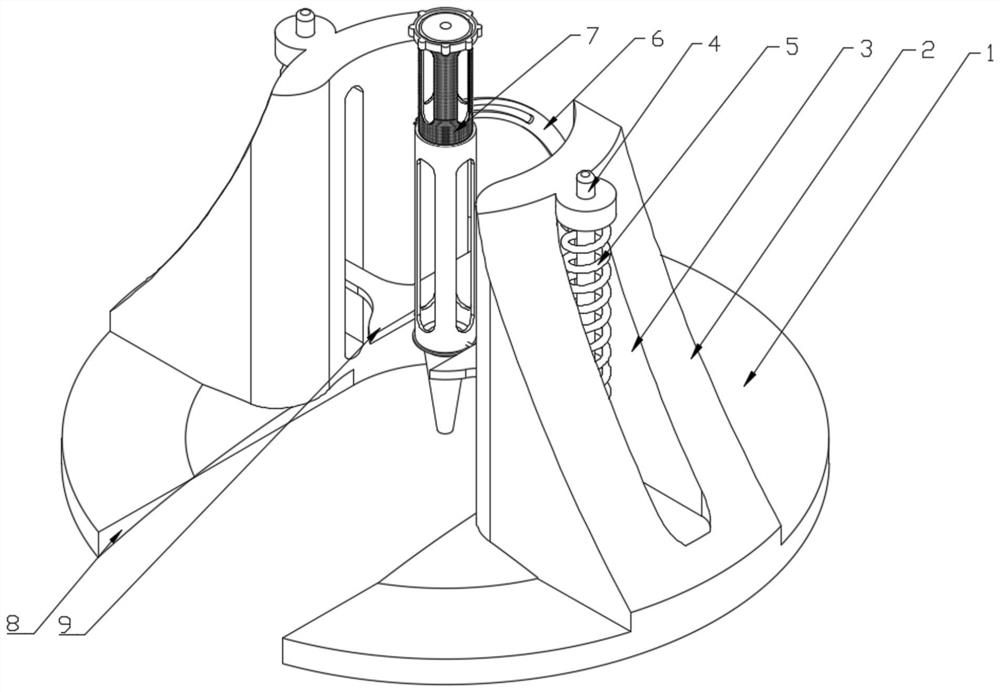
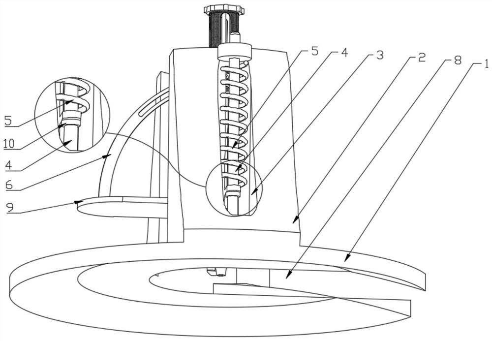
[0045] The present invention provides a puncture device suitable for epidural cavity and epidural catheter placement in anesthesiology department. Symmetrical arrangement, the outer sides of the two fixed seats 2 are provided with opening slots 3; the opening slots 3 are provided with sliding rods 4; the two sliding rods 4 are jointly connected with a sliding plate 9 ; The sliding plate 9 is movably connected with a puncturing mechanism 7, and the puncturing mechanism 7 is also movably connected with the inclination angle adjustment frame 6; the inclination angle adjustment frame 6 is fixed on the sliding plate 9;

[0046] The bottom of the chassis 1 is set in an arc shape, and the chassis 1 is provided with a U-shaped groove 8; the sliding plate 9 is also provided with a U-shaped groove, which is consistent with the opening direction of the U-shaped groove 8 on the chassis 1. ;

[0047] The two described sliding bars 4 are sleeved with top tightening springs 5, and the two d...

Embodiment 2

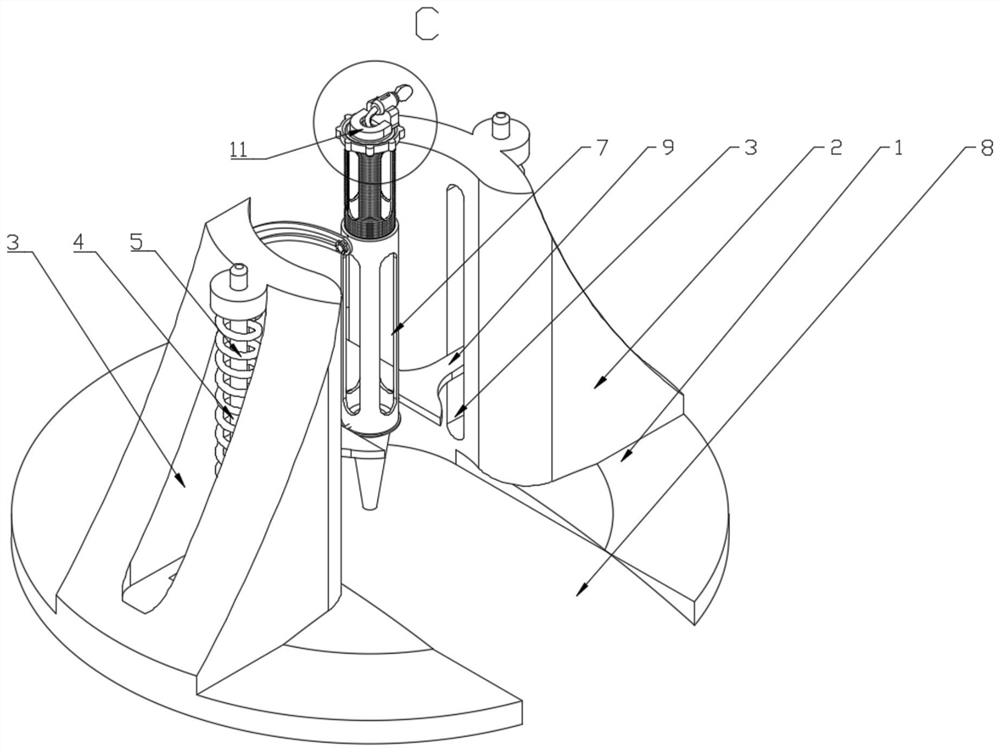
[0055] In this embodiment, an auxiliary epidural puncture assembly 11 is fixedly installed on the top of the puncture mechanism 7 ; the auxiliary epidural puncture assembly 11 includes a U-shaped seat 111 , which is clamped inside the U-shaped seat 111 There is a clamping seat 112, and a drug cartridge 113 is arranged above the clamping seat 112; Balloon 114 .

[0056] In this embodiment, an air inlet valve 117 is provided at the end of the balloon 114 away from the drug cartridge 113 , and a one-way valve 118 is provided at the connecting end of the balloon 114 and the drug cartridge 113 ; A float 119 is provided and a see-through window 115 is provided on top of the cartridge 113 .

[0057] Specifically, after the puncture is completed, the medical staff presses the balloon 114 hard, the gas pushes open the one-way valve 118, and pushes the liquid medicine to be injected into the puncture needle 77. At this time, the floating ball 119 also moves to the medicine delivery tub...

Embodiment 3

[0059] In this embodiment, the top of the puncture mechanism 7 is fixedly installed with an auxiliary component for placing an epidural catheter 14 , and the auxiliary component 14 for placing an epidural catheter includes a fixing cylinder 141 , and the inner wall of the fixing cylinder 141 is provided with a Two symmetrically arranged chutes 142 ; the fixed cylinder 141 is provided with two symmetrically arranged clamping blocks 144 , and the two clamping blocks 144 are slidably connected to each other through a T-bar 145 . inside the chute 142.

[0060] Specifically, when puncturing the epidural catheter, first adjust the inclination of the puncture mechanism 7 according to the needle insertion angle. When adjusting, first loosen the lock nut 12 and tilt the puncture mechanism 7 to one side until the scale indicating block 13 is indicated on the appropriate angle mark; then tighten the lock nut 12, and then fit the chassis 1 on the back of the patient, the puncture mechanis...


PUM


Abstract

The invention provides a puncture device suitable for an epidural space and an epidural catheter in the anesthesiology department, and relates to the technical field of anesthesia appliances, the puncture device suitable for the epidural space and the epidural catheter in the anesthesiology department comprises a base plate, two fixing seats of the base plate are symmetrically arranged, and open grooves are formed in the outer sides of the two fixing seats; a sliding rod is arranged in the open slot; a sliding plate is connected to the two sliding rods; during puncturing, the puncturing mechanism is in a vertical state, then the base plate is attached to the back of a patient, the puncturing mechanism is aligned with the midpoint of a spinous process gap of the patient, then the plum blossom handle drives the screwing pipe to move forwards slowly, after the screwing pipe is screwed into the connecting cylinder continuously, a puncturing needle penetrates through the conical auxiliary pipe firstly, and then the puncturing needle is inserted into the conical auxiliary pipe. The puncture needle is arranged on the waist of a patient and then slowly punctures the skin of the patient, so that puncture of the waist of the patient is achieved, the patient can be stably punctured in the process, the puncture needle cannot deviate, and the puncture needle cannot be bent under the assistance of the conical auxiliary tube.

Description

technical field [0001] The invention belongs to the technical field of anesthesia appliances, and in particular relates to a puncture device suitable for an epidural cavity and an epidural catheter in an anesthesiology department. Background technique [0002] Spinal puncture is an essential skill for performing spinal anesthesia. According to the classification of spinal anesthesia, continuous epidural nerve block (referred to as Lianji), subarachnoid nerve block (the puncture site is often in the lumbar spine, so it is referred to as spinal anesthesia), and the combined application of the former two. Combined epidural anesthesia and spinal canal puncture are also divided into combined epidural anesthesia, spinal anesthesia, and combined spinal-epidural anesthesia. [0003] Epidural puncture: Use the thumb and index finger of the left hand to fix the skin of the puncture point, position the epidural puncture needle at the midpoint of the spinous process space, perpendicula...

Claims


Application Information

Patent Timeline
Patent Type & Authority Applications(China)
IPC IPC(8): A61B17/34
CPCA61B17/3401A61B17/3415A61B17/3417A61B17/3494A61B2017/3454
Inventor 常新会徐宏超
Owner NANYANG SECOND GENERAL HOSPITAL
Why Eureka
Try Eureka