Supercharge Your Innovation With Domain-Expert AI Agents!

Casting device and casting method for centrifugal casting detection of boiler for casting

A centrifugal casting and boiler technology, applied in the direction of measuring devices, casting molding equipment, casting molds, etc., can solve problems such as segmentation, inability to flow, affect casting quality, etc., achieve uniform spraying, reduce resistance, and save spraying time.

Pending Publication Date: 2022-07-15
裴振国
View PDF0 Cites 0 Cited by
  • Summary
  • Abstract
  • Description
  • Claims
  • Application Information

AI Technical Summary

Problems solved by technology

[0003] The centrifugal casting machine is composed of a main machine, a pouring trolley, a pick-up mechanism, a spraying mechanism and a water-cooling mechanism. The melt is cast into a cylindrical shape under the action of the casting process. During the casting process, the surface of the mold is cooled by a water cooling mechanism to speed up the molding of the casting. However, when the existing casting machine is in operation, the melt begins to cool as soon as it is injected into the mold, resulting in The melt in the first half of the mold is rapidly formed, but cannot flow to the second half of the mold, which will cause the phenomenon of segmentation after the casting is formed, which will affect the casting quality

Method used


Image

  • Casting device and casting method for centrifugal casting detection of boiler for casting
  • Casting device and casting method for centrifugal casting detection of boiler for casting
  • Casting device and casting method for centrifugal casting detection of boiler for casting

Examples


Embodiment 1

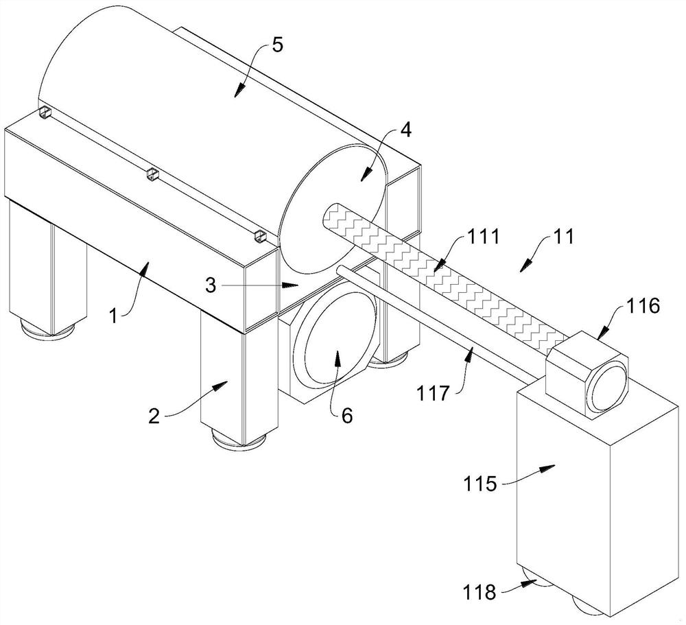
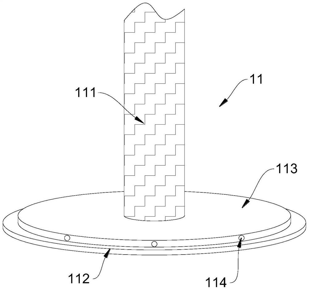
[0041] like Figure 1 to Figure 3 Shown: the trigger mechanism 11 includes a first screw rod 111 screwed through the right side of the mold 4 , the left side of the first screw rod 111 is rotatably connected with a rear baffle 112 , and the right side of the first screw rod 111 A second motor 116 is rotatably connected, and the lower end of the second motor 116 is fixedly connected with a base 115, the lower end of the base 115 is provided with a pulley 118, and the upper left side of the base 115 is provided with a switch for controlling the water cooling mechanism, and the switch A triggering rope 117 is fixedly connected with the bracket 3 .

[0042] When working, during the casting process, with the rotation of the mold 4, since the mold 4 and the first screw rod 111 are connected by a screw drive, and the first screw rod 111 is restricted by the second motor 116 and cannot rotate, when the mold 4 During rotation, the first screw rod 111 is driven to move from the left side...

Embodiment 2

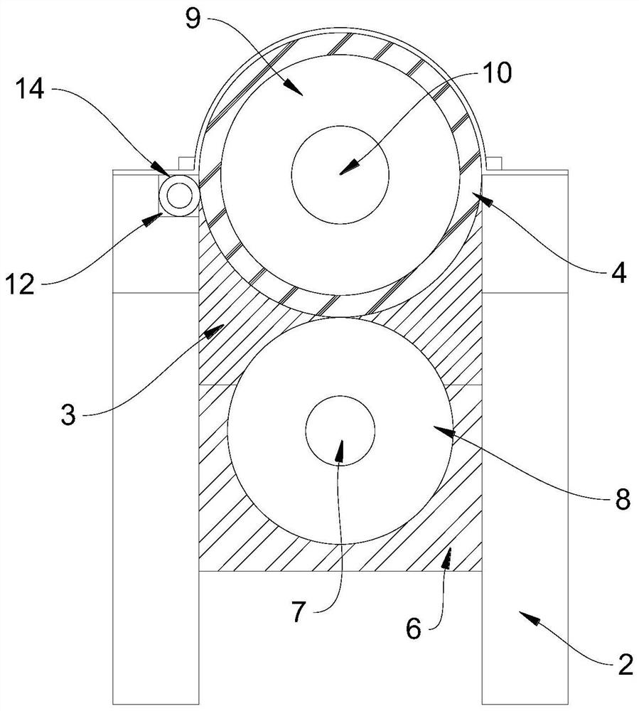
[0047] like figure 2 and Figure 5 Shown: the trigger mechanism 11 further includes a cavity 12 opened at the front of the workbench 1, and the interior of the cavity 12 is fixedly connected with a second screw rod 13, and the outer screw sleeve of the second screw rod 13 is screwed with The spiral sleeve 14 is in close contact with the surface of the mold 4, and the inner wall of the right side of the cavity 12 is provided with a switch for controlling the water cooling mechanism.

[0048] During operation, when the mold 4 rotates, it contacts with the screw sleeve 14 to drive the screw sleeve 14 to rotate. Since the screw sleeve 14 is connected with the second screw rod 13 in a screw drive, when the screw sleeve 14 rotates, it rotates along the second screw. The rod 13 is displaced to the right until the screw sleeve 14 moves to the far right of the second screw rod 13, indicating that the melt has filled the inner wall of the mold 4. At this time, the screw sleeve 14 sque...


PUM


Abstract

The invention discloses a boiler centrifugal casting detection casting device for casting and a casting method.The boiler centrifugal casting detection casting device for casting comprises a workbench, supporting columns are fixedly connected to the corners of the lower end of the workbench, and a bracket is fixedly connected to the middle of the upper end of the workbench; the upper end of the bracket is rotatably connected with a mold, the upper end of the mold is provided with a pressing plate in bolted connection with the workbench, the right side of the lower end of the workbench is fixedly connected with a first motor, the left side of the first motor is rotatably connected with a machine shaft, and the left side of the machine shaft is fixedly connected with a power disc. The upper portion of the power disc penetrates through the workbench and the bracket to be attached to the mold, the left side of the mold is movably connected with a front baffle, the water cooling mechanism can be triggered to be started after melt is completely distributed on the inner wall of the mold, and the phenomenon that the melt cooled too early is solidified and shaped at the front half section of the mold, and consequently a casting is segmented after being formed is prevented.

Description

technical field [0001] The invention relates to the field of centrifugal casting, and more particularly, to a casting device and a casting method for centrifugal casting detection of a boiler for casting. Background technique [0002] A casting method in which liquid metal is poured into a rotating mold, filled and solidified into a casting under the action of centrifugal force. The machine used for centrifugal casting is called centrifugal casting machine; [0003] The centrifugal casting machine consists of a centrifugal casting machine, which consists of a main machine, a pouring trolley, a pick-up mechanism, a spraying mechanism and a water cooling mechanism. The molten metal is cast into a cylindrical shape under the action of the casting process. During the casting process, the surface of the mold is cooled by a water-cooling mechanism to speed up the molding of the casting. The molten liquid in the first half of the mold is rapidly formed, and cannot flow to the sec...

Claims


Application Information

Patent Timeline
IPC IPC(8): B22D13/10B22D13/12B22C3/00G01P3/00
CPCB22D13/12B22D13/105B22C3/00G01P3/00
Inventor 裴振国
Owner 裴振国
Features
  • R&D
  • Intellectual Property
  • Life Sciences
  • Materials
  • Tech Scout
  • Unparalleled Data Quality
  • Higher Quality Content
  • 60% Fewer Hallucinations
Learn More