Industrial robot joint friction compensation method based on disturbance observation

A technology of industrial robots and disturbance observers, applied in manipulators, manufacturing tools, program-controlled manipulators, etc., can solve problems such as deterioration of friction compensation effects and inconsistencies in observer performance, and achieve improved synchronization and rhythm, good results, and improved Effects of Accuracy and Smoothness

Active Publication Date: 2022-07-15
CHENGDU CRP ROBOT TECH CO LTD
View PDF7 Cites 3 Cited by
  • Summary
  • Abstract
  • Description
  • Claims
  • Application Information

AI Technical Summary

Problems solved by technology

[0009] The parameters that need to be used in the observer include the load moment of inertia of each joint, that is, the observation method depends on the load moment of inertia of each joint, and the load moment of inertia changes in real time during the movement of the robot, and the changing load moment of inertia will cause the observer The inconsistency of performance under different working conditions or attitudes deteriorates the effect of friction compensation

Method used


Image

  • Industrial robot joint friction compensation method based on disturbance observation
  • Industrial robot joint friction compensation method based on disturbance observation
  • Industrial robot joint friction compensation method based on disturbance observation

Examples


Embodiment 1

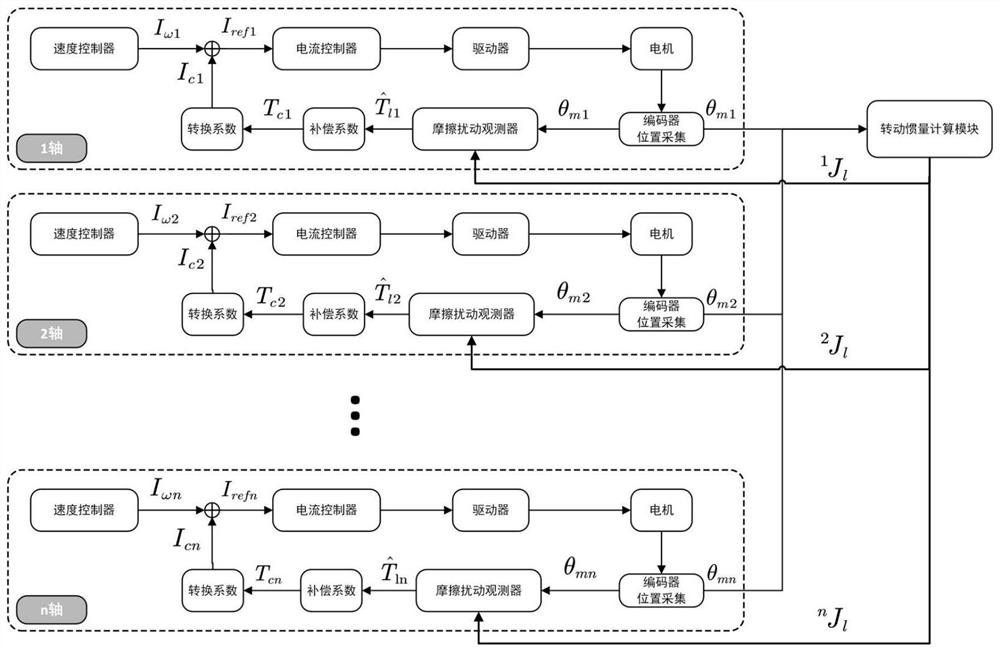
[0055] see figure 1 , the present embodiment discloses a method for compensating the joint friction of an industrial robot based on disturbance observation, including the following contents:

[0056] 1) Collect the motor rotor angle θ of each joint motor encoder mi ;

[0057] 2) Set the rotor angle θ of each joint motor mi Input the moment of inertia calculation module, which outputs the moment of inertia of the total load converted to the motor side by each joint i J l ;

[0058] 3) Set the total load moment of inertia on the motor side i J l and the motor rotor angle θ mi Enter the disturbance observer module to get the observed value of the friction torque

[0059] 4) The observed value of friction torque Multiply the compensation coefficient k c Get the compensation torque T ci ;

[0060] 5) will compensate torque T ci Converted to friction compensation current I ci , if the T ci divided by the torque-current conversion factor k t ,Right now or the T ...


PUM


Abstract

The invention discloses an industrial robot joint friction compensation method based on disturbance observation, and relates to the technical field of industrial robots, and the method comprises the following steps: 1) collecting the motor rotor angle of each joint motor encoder; (2) the motor rotor angles of all the joints are input into a rotational inertia calculation module, and the rotational inertia calculation module outputs the total load rotational inertia, converted to the motor side, of all the joints; 3) inputting the total load rotational inertia of the motor side and the motor rotor angle into a disturbance observer module to obtain an observed value of the friction torque; and converting the observed value into a friction compensation current, and then adding the friction compensation current into a torque current instruction in a servo controller to realize friction compensation. Compensation of robot joint friction force can be achieved, joint speed errors are reduced, the dynamic performance of a joint motor is improved, and the track precision of the robot is improved.

Description

technical field [0001] The invention relates to the technical field of industrial robots, in particular to a method for compensating joint friction of industrial robots based on disturbance observation. Background technique [0002] The robot works with the continuous movement of each joint, and there are nonlinear friction links in the joint movement process, which seriously affects the dynamic and static performance of the robot system. It is mainly manifested in the generation of control dead zone, reduction of angular resolution and repeatability, creeping phenomenon at low speed, large error in steady state, limit cycle oscillation or stop-slip (Sick-slip) motion, etc. The friction force is often compensated by means of torque feedforward. In the prior art, the friction force compensation data is mainly obtained by calculation based on a friction force model, or by numerical observation of the friction force by an observer. [0003] The method of directly observing the...

Claims


Application Information

Patent Timeline
Patent Type & Authority Applications(China)
IPC IPC(8): B25J9/16
CPCB25J9/1641B25J9/1607
Inventor 陶良驹徐纯科朱路生
Owner CHENGDU CRP ROBOT TECH CO LTD
Why Eureka
Try Eureka