
Electromagnetic switch

An electromagnetic switch and cover technology, which is applied in the field of electromagnetic switches, can solve the problems of increased motor insecurity and maintenance costs, failure of electromagnetic switch contacts, and failure of motors to work normally, achieving simple structure, reliable performance, and prevention of overheating. The effect of early failure

Pending Publication Date: 2022-07-15
成都华川电装有限责任公司
View PDF0 Cites 0 Cited by
  • Summary
  • Abstract
  • Description
  • Claims
  • Application Information

AI Technical Summary

Problems solved by technology

[0003] Due to the complexity of the automotive environment, some northern provinces in China and some foreign regions have an extreme environment of low temperature, large temperature difference and high humidity in winter. After the vehicle is turned off and placed in a low temperature and high humidity environment for a long time, the engine will start As a relatively closed space inside the electromechanical electromagnetic switch, it will start to dissipate heat to the outside world. Since the electromagnetic switch is mainly made of metal and plastic materials (the electromagnetic switch shell, dynamic and static iron core and dynamic and static contacts are metal; the electromagnetic switch end cover is plastic ) together, and metal loses heat faster than plastic, and the water vapor in the electromagnetic switch is not discharged in time, and condensation phenomenon easily occurs in the electromagnetic switch cavity. Corrosion of the moving iron core eventually causes the contact of the electromagnetic switch to fail to conduct or the moving iron core is jammed and unable to return to its position in time. Finally, the motor cannot work normally, which increases the unsafety of the motor and the maintenance cost

Method used


Image

  • Electromagnetic switch
  • Electromagnetic switch
  • Electromagnetic switch

Examples


Embodiment Construction

[0017] The present invention will be described in further detail below with reference to the accompanying drawings and specific embodiments.

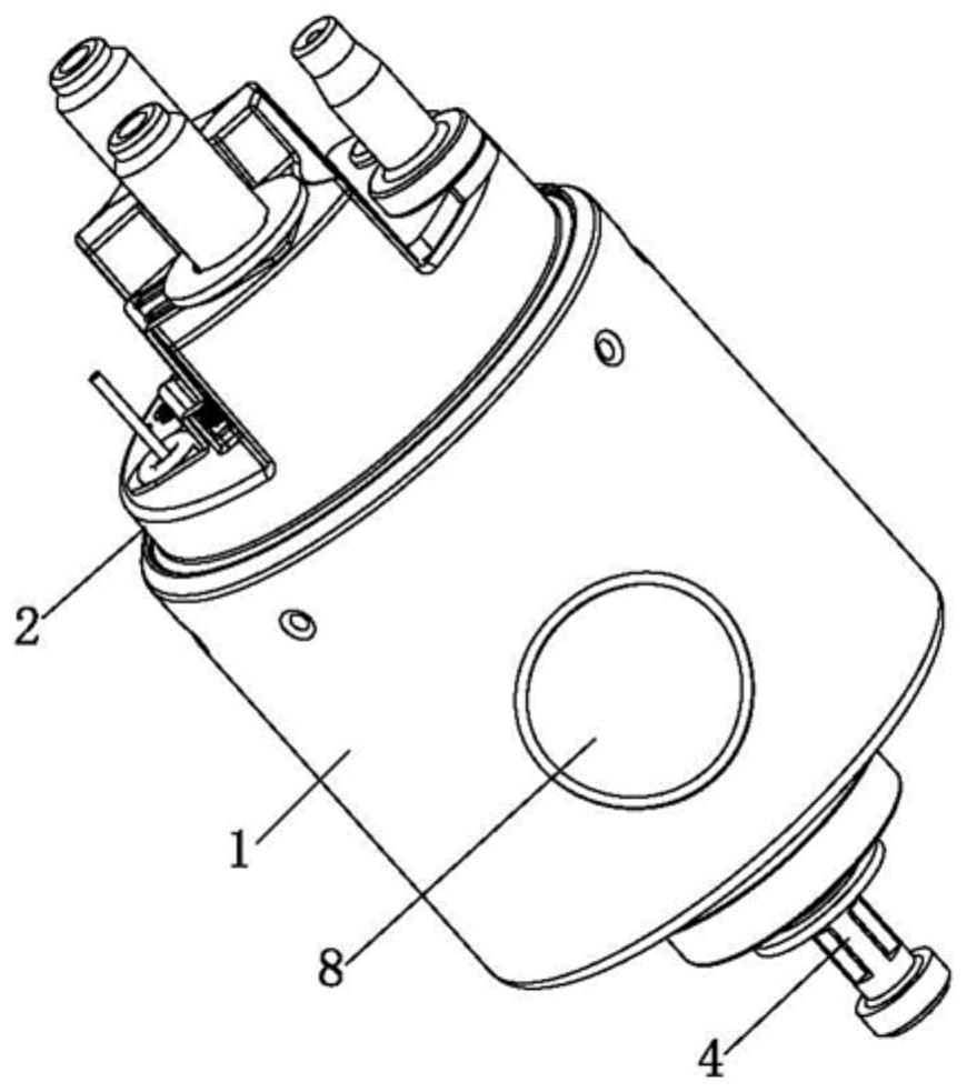
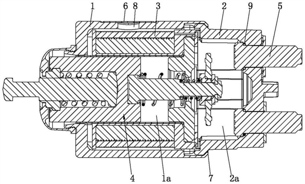
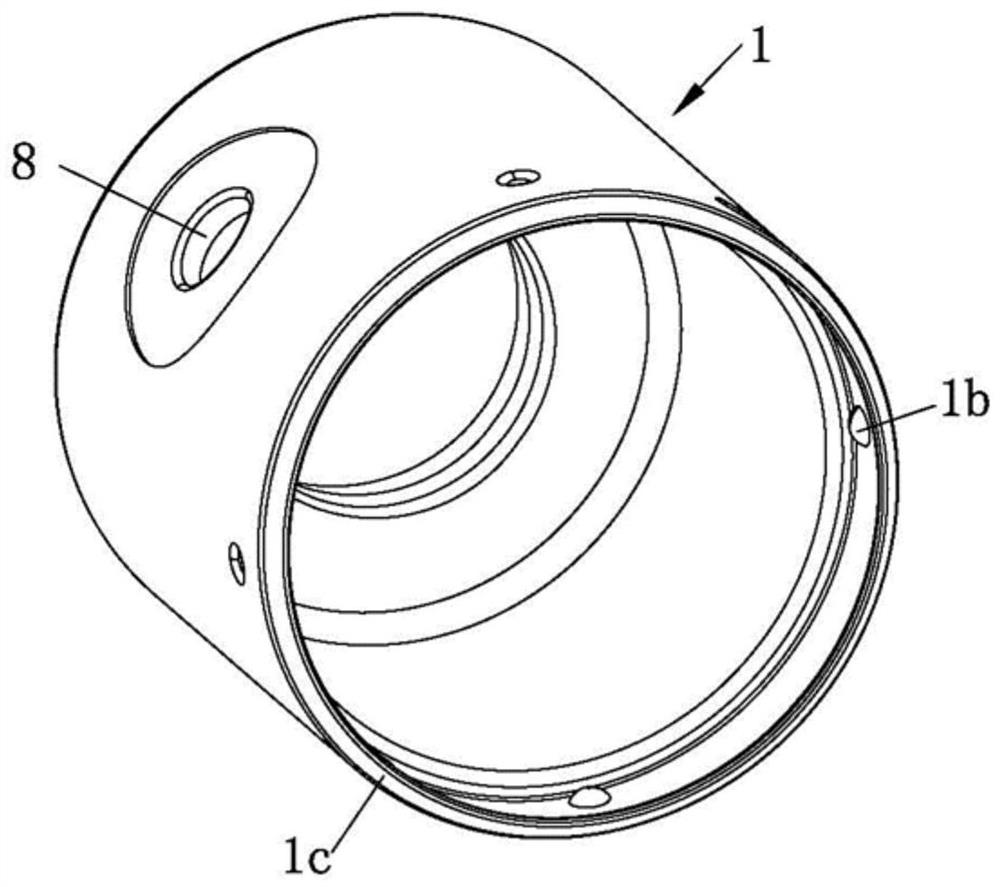
[0018] An electromagnetic switch, including a cover 1, an end cover 2, a coil assembly 3, a coil bobbin 4b, a moving iron core assembly 4, a static contact 5, a water-permeable component 6, and a sealing layer 7. The relationship between them is explained in detail:

[0019] The cover 1 has an axial first stepped through hole, and the end cover 2 is provided with a cavity 2a. After one end of the cover 1 is combined and fixed with one end of the end cover 2, a first step is formed between the cover 1 and the end cover 2 The accommodating cavity 1a, the first accommodating cavity 1a is used for accommodating at least a part of the coil assembly 3 , the movable iron core assembly 4 and the static contact 5 .

[0020] As mentioned, the end cover 2 is made of ammonia-free thermosetting plastic, which can withstand high and low temperature,...


PUM


Abstract

One end of a movable iron core assembly and one end of a static contact are located in a first containing cavity, the other end of the movable iron core assembly is exposed out of an outer cover, the static contact is fixed to an end cover, the other end of the static contact penetrates through the end cover and is exposed out of the end cover, and the electromagnetic switch further comprises a waterproof ventilation part and a sealing layer. The outer cover and / or the end cover are / is provided with ventilation holes, the waterproof ventilation component is used for releasing water vapor in the first containing cavity after being matched with the ventilation holes, and a sealing layer used for sealing the combination portion of the outer cover and the end cover is arranged at one end of the outer cover and one end of the end cover. In a low-temperature and high-humidity environment, the temperature difference inside and outside the electromagnetic switch can be balanced, the inner cavity of the electromagnetic switch is communicated with the outside, and the temperature difference between the inner cavity of the electromagnetic switch and the outside is reduced.

Description

technical field [0001] The invention relates to the technical field of automobile starters, in particular to an electromagnetic switch used for automobile starters. Background technique [0002] The function of the starter is to convert the electrical energy of the battery into mechanical energy and drive the engine flywheel to rotate to start the engine. The starter consists of three parts: the motor body, the transmission mechanism and the control mechanism. As a control mechanism, the electromagnetic switch is one of the three major components of the starter. Its working principle is that after the coil is energized, an electromagnetic suction force is generated, which makes the movable iron core move. On the other hand, the dynamic and static contacts of the switch are pushed to connect, so that the motor body is energized and operated, thereby driving the engine to start. [0003] Due to the complexity of the automotive environmental conditions, the winter climate in ...

Claims


Application Information

Patent Timeline
IPC IPC(8): H01H36/00H01H9/04
CPCH01H36/00H01H9/04
Inventor 刘慧芳陈鹏宇许钰任二伟
Owner 成都华川电装有限责任公司
Learn More