Rotating speed control method and synchronous motor for automobile air conditioner compressor

A synchronous motor and speed control technology, which is applied in the direction of controlling generators, electromechanical brakes, and electromechanical transmissions, can solve the problems of synchronous motor speed fluctuations, damage to compressor winding excitation devices, and inability to install speed sensors. The effect of out-of-step state, suppression of speed fluctuation, and stability

Active Publication Date: 2022-07-15
CHANGZHOU CHANGHUA ELECTRICAL MOTOR
View PDF4 Cites 0 Cited by
  • Summary
  • Abstract
  • Description
  • Claims
  • Application Information

AI Technical Summary

Problems solved by technology

In the control of the traditional permanent magnet synchronous motor, in order to obtain the precise position and speed of the rotor, the most common method is to install a mechanical speed sensor on the rotor shaft, but in the inverter air conditioner, the permanent magnet synchronous motor is in a sealed compression Inside the machine, the temperature inside the compressor exceeds 120 degrees Celsius, and it is filled with highly corrosive high-pressure refrigerant, so it is impossible to install a speed sensor
[0005] In the permanent magnet synchronous motor-air conditioner compressor load system with speed sensorless vector control, the speed of the synchronous motor fluctuates due to the large-scale change of the load torque, which may cause the synchronous motor to be out of step. If the synchronous motor is long The time is out of step, which will damage the compressor winding or excitation device, resulting in the compressor not working properly

Method used


Image

  • Rotating speed control method and synchronous motor for automobile air conditioner compressor
  • Rotating speed control method and synchronous motor for automobile air conditioner compressor
  • Rotating speed control method and synchronous motor for automobile air conditioner compressor

Examples


Embodiment Construction

[0031] The technical solutions in the embodiments of the present invention will be clearly and completely described below with reference to the accompanying drawings in the embodiments of the present invention. Obviously, the described embodiments are only a part of the embodiments of the present invention, rather than all the embodiments.

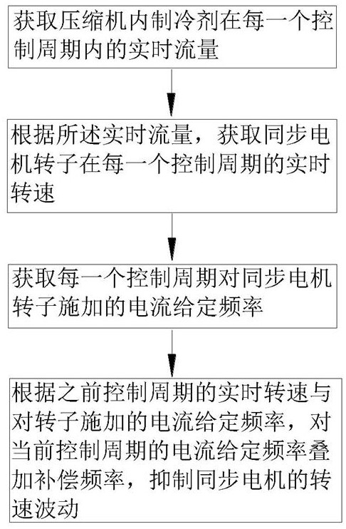
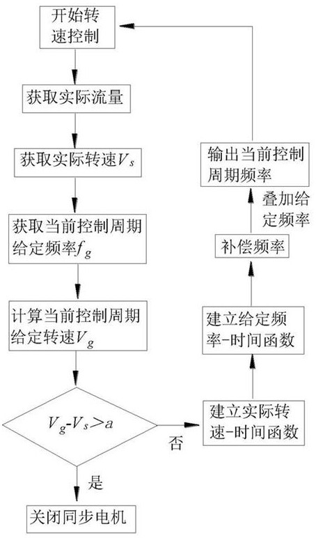
[0032] like figure 1 As shown: a speed control method, comprising the following steps:

[0033] Obtain the actual flow of refrigerant in the compressor in each control cycle;

[0034] According to the actual flow, the actual speed of the rotor of the synchronous motor in each control cycle is obtained, and the relationship function between the actual speed and time is established;

[0035] Obtain the given frequency of the current applied to the rotor of the synchronous motor in each control cycle, and establish a given frequency-time relationship function;

[0036] According to the relationship function between actual speed and time and...


PUM


Abstract

The invention relates to the technical field of synchronous motors, in particular to a rotating speed control method and a synchronous motor for an automobile air conditioner compressor, and the method comprises the following steps: obtaining the actual flow of a refrigerant in the compressor in each control period; according to the actual flow, the actual rotating speed of the synchronous motor rotor in each control period is obtained; obtaining a given frequency applied to a synchronous motor rotor in each control period; and according to the actual rotating speed of the previous control period and the given frequency applied to the rotor, superposing the compensation frequency on the current given frequency of the current control period, and inhibiting the rotating speed fluctuation of the synchronous motor. According to the method, the flow of the refrigerant is converted into the actual rotating speed of the rotor of the synchronous motor, the compensation frequency is superposed on the given current frequency of the current control period, closed-loop control is carried out, and rotating speed fluctuation of the synchronous motor is restrained, so that the synchronous motor is effectively prevented from being in an out-of-step state, and a compressor winding or an excitation device is protected; the working stability of the compressor is ensured.

Description

technical field [0001] The invention relates to the technical field of synchronous motors, in particular to a rotational speed control method and a synchronous motor for an automobile air-conditioning compressor. Background technique [0002] With the active promotion of energy-saving and consumption-reducing technologies around the world, inverter air conditioners have gradually attracted the attention of the market because of their unique advantages. [0003] Due to the characteristics of frequency converter power supply and the particularity of compressor operation, ordinary asynchronous motors often have problems such as low efficiency and high noise, and it is difficult to achieve better operating performance. Permanent magnet synchronous motor has the characteristics of simple structure, small size, light weight, low loss and high efficiency. Compared with the asynchronous motor, because it does not need reactive excitation current, it has high efficiency, high power ...

Claims


Application Information

Patent Timeline
Patent Type & Authority Applications(China)
IPC IPC(8): H02P6/06H02P6/08H02P21/18H02P21/24H02P25/024H02H7/093
CPCH02P6/06H02P6/08H02P21/18H02P21/24H02P25/024H02H7/0805H02H7/0844H02H7/093H02P2203/03H02P2203/09H02P2207/05Y02B30/70
Inventor 曹飞龙
Owner CHANGZHOU CHANGHUA ELECTRICAL MOTOR
Why Eureka
Try Eureka