[0035] Example 1:
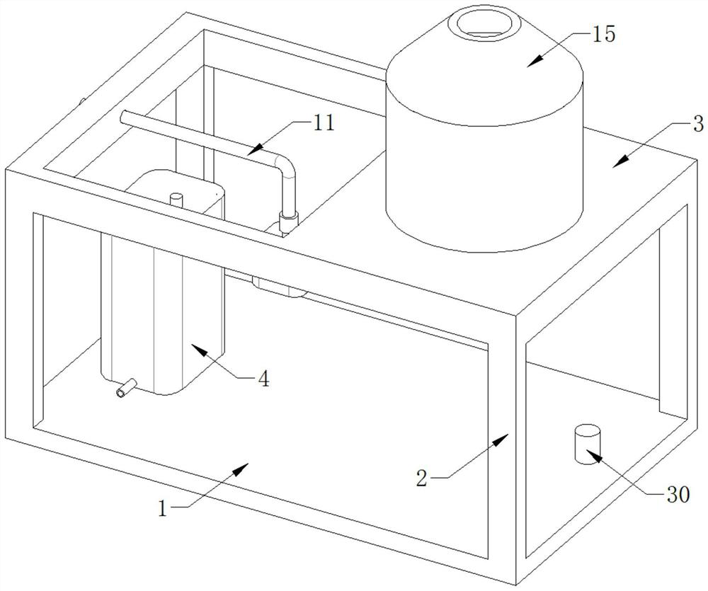
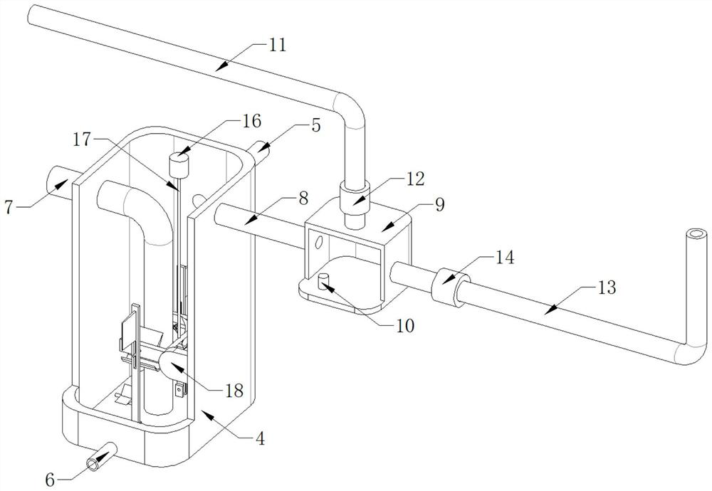
[0036] 3. See Figure 1-5 , A purification and emission device for flue gas desulfurization and denitrification, comprising a bottom plate 1, a support leg 2 is fixedly installed at the four corners of the top side of the bottom plate 1, a top plate 3 is fixedly installed on the top side of the support leg 2, and an exhaust tower is fixedly installed on the top side of the top plate 3 15, a reactor 4 is fixedly installed on the top side of the bottom plate 1, the interior of the reactor 4 is filled with sodium hydroxide absorbing liquid, and one side of the reactor 4 is provided with a gas delivery mechanism, and the gas delivery mechanism is used to transport the absorbed flue gas;
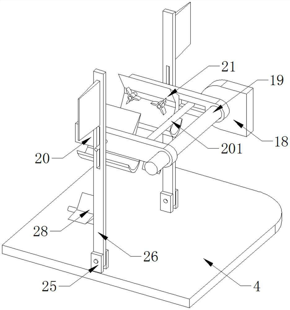
[0037] The top side of the reactor 4 is provided with a telescopic mechanism, the inner wall of the reactor 4 is provided with a support mechanism, and the bottom inner wall of the reactor 4 is provided with a shaking mechanism, and the telescopic mechanism drives the shaking mechanism to shake through the support mechanism;
[0038] The position of the top side of the bottom plate 1 away from the reactor 4 is fixedly installed with a processor 30, and the processor is used to control the opening or closing of the electromagnetic valve in the corresponding gas delivery mechanism according to the nitrogen and sulfur content in the flue gas. The reactor 4 A liquid inlet pipe 5 is fixedly installed on one side, a liquid outlet pipe 6 is fixedly installed on the other side of the reactor 4, and an air inlet hole 7 is fixedly installed on the side of the reactor 4 away from the support mechanism, and the gas transmission mechanism is used to transport the absorbed The flue gas, the telescopic mechanism drives the shaking mechanism to shake through the support mechanism.
[0039] see figure 2 , the gas delivery mechanism includes a gas outlet pipe 8, one side of the gas outlet pipe 8 is fixedly connected with the reactor 4, the other side of the gas outlet pipe 8 is fixedly installed with an exchange block 9, and the bottom inner wall of the exchange block 9 is fixedly installed with a chemical sensor 10, and the chemical sensor 10 is connected with The processor 30 is electrically connected, the air return pipe 11 is fixedly installed on the top side of the exchange block 9 , the air return pipe 11 penetrates the top plate 3 , the outer wall of the air return pipe 11 is fixedly installed with a vertical solenoid valve 12 , and the vertical solenoid valve 12 is electrically connected to the processor 30 . If the nitrogen and sulfur content in the flue gas exceeds the standard, the vertical solenoid valve 12 is in an open state and the horizontal solenoid valve 14 is in a closed state under the control of the processor 30, and the flue gas can be returned to the flue gas generation furnace through the gas return pipe 11. , which is convenient for desulfurization and denitrification again.
[0040] see figure 2 , the side of the exchange block 9 away from the gas outlet pipe 8 is fixedly installed with a gas release pipe 13, the outer wall of the gas release pipe 13 is fixedly installed with a horizontal solenoid valve 14, the horizontal solenoid valve 14 is electrically connected with the processor 30, and the other side of the gas release pipe 13 is connected to The exhaust tower 15 is fixedly connected. If the nitrogen and sulfur content in the flue gas does not exceed the standard, under the control of the processor 30, the vertical solenoid valve 12 is in a closed state, and the horizontal solenoid valve 14 is in an open state, and the flue gas can enter through the exhaust pipe 13. The inside of the exhaust tower 15 is then discharged into the atmosphere, and the pollution-free emission of flue gas is successfully achieved.
[0041] see figure 2 , the telescopic mechanism includes a cylinder 16, the bottom side of the cylinder 16 is fixedly connected with the reactor 4, the output end of the cylinder 16 is fixedly installed with a telescopic rod 17, and the telescopic rod 17 extends to the interior of the reactor 4, turn on the power supply of the cylinder 16, let the cylinder 16 drives the telescopic rod 17 to move back and forth in the vertical direction, which is beneficial for the shaking mechanism to stir the absorbing liquid.
[0042] see image 3 and Figure 4, the support mechanism includes a fixed plate 18, one side of the fixed plate 18 is fixedly connected with the inner wall of the reactor 4, a fixed rod 19 is fixedly installed on the opposite side of the two fixed plates 18, and the outer wall of the fixed rod 19 is rotatably connected with a rotating plate 20, the two rotating plates 20 The opposite side is slidably connected with a lifting sliding rod 201, the outer wall of the lifting sliding rod 201 is fixedly connected with the telescopic rod 17, the opposite side of the rotating plate 20 is fixedly installed with a V-shaped plate 21, and the opposite side of the V-shaped plate 21 is rotatably connected with an inner impeller 22, V The arc-shaped plate 23 is fixedly installed on the side of the mold plate 21 that is far away from each other, and the sliding rod 24 is fixedly installed on the side of the rotating plate 20 that is far away from each other. The plate 21 stirs the sodium hydroxide absorbing liquid, and simultaneously rotating the connected inner impeller 22 and the arc-shaped arc-shaped plate 23 can speed up the internal fluidity of the absorbing liquid.
[0043] see Figure 5 , the shaking mechanism includes a limit block 25, the bottom side of the limit block 25 is fixedly connected with the reactor 4, the inner wall of the limit block 25 is rotatably connected with a vertical rotating plate 26, and one side of the vertical rotating plate 26 is provided with a sliding groove 27, sliding The groove 27 is slidably connected with the sliding rod 24, the outer impeller 28 is rotatably connected to one side of the vertical rotating plate 26, the mixing plate 29 is fixedly installed on the side of the two vertical rotating plates 26 away from each other, and the sliding rod 24 drives the vertical rotating plate 26 rotates around the limit block 25, which is beneficial for the edge of the mixing plate 29 to stir the absorbing liquid, so as to achieve the purpose of mixing the absorbing liquid evenly.
[0044] When in use: the sodium hydroxide absorbing liquid is transported from the liquid inlet pipe 5 to the inside of the reactor 4, the liquid outlet pipe 6 is in a closed state, and then the flue gas is passed into the reactor 4 from the gas inlet hole 7, at this time Turn on the power supply of the air cylinder 16, let the air cylinder 16 drive the telescopic rod 17 to move back and forth in the vertical direction, and then drive the rotating plate 20 to rotate around the fixed rod 19 through the lifting sliding rod 201, which is beneficial for the V-shaped plate 21 to absorb the sodium hydroxide. Stirring and rotating the connected inner impeller 22 and the arc-shaped arc-shaped plate 23 at the same time can speed up the internal fluidity of the absorbing liquid. The absorption liquid is stirred to achieve the purpose of mixing the absorption liquid evenly, and then the flue gas that has been desulfurized and denitrified enters the interior of the exchange block 9 through the gas outlet pipe 8. After the detection by the chemical sensor 10, if the nitrogen and sulfur content in the flue gas does not exceed the standard, Under the control of the processor 30, the vertical solenoid valve 12 is in a closed state, and the horizontal solenoid valve 14 is in an open state, and the flue gas can enter the exhaust tower 15 through the exhaust pipe 13, and then be discharged into the atmosphere. If the sulfur content exceeds the standard, the vertical solenoid valve 12 is open and the horizontal solenoid valve 14 is closed under the control of the processor 30. The flue gas can be returned to the flue gas generation furnace through the gas return pipe 11, which is convenient for desulfurization and denitrification again.