Electrolytic machining method, terminal and storage medium

A processing method and electrolyte technology, applied in the supply of processing working medium, electrochemical processing equipment, metal processing equipment, etc., can solve the problems of inconvenient control, hindering processing work, burning processing electrodes and workpieces, etc., and improve efficiency , prevent short circuit, enhance the effect of automatic degree

Inactive Publication Date: 2022-07-22
刘宇
View PDF5 Cites 0 Cited by
  • Summary
  • Abstract
  • Description
  • Claims
  • Application Information

AI Technical Summary

Problems solved by technology

[0003] In electrolytic machining, when the workpiece needs to be processed into a porous structure, a single electrode assembly is used to process one by one, which is inefficient; multiple electrode assemblies are used to process simultaneously, and there is a problem of inconvenient control; at the same time, gas will be generated during electrolytic machining , such as Cl2, Br2 and other harmful gases, if not collected and concentrated treatment will pollute the environment and affect the physical and mental health of the staff; as the depth of the processing hole increases, the electrolyte in the processing gap will produce some insoluble products, Such as Fe(OH)2, Fe(OH)3, etc., become more and more difficult to discharge, and if they are not discharged in time, they will gradually flocculate, affecting the flow of electrolyte in the processing gap and hindering normal processing; and in the deep processing In the process of drilling, when the machining electrode is repeatedly retracted to increase the machining gap and promote the discharge of the electrolyte in the machining gap, it is necessary to avoid the swing of the machining electrode to prevent the machining electrode from directly contacting the inner wall of the workpiece, resulting in a short circuit between the machining electrode and the workpiece. Burn out machining electrodes and workpieces

Method used


Image

  • Electrolytic machining method, terminal and storage medium
  • Electrolytic machining method, terminal and storage medium
  • Electrolytic machining method, terminal and storage medium

Examples


Embodiment Construction

[0064] In order to make the objectives, technical solutions and advantages of the present invention clearer, the present invention will be further described in detail below with reference to the accompanying drawings and embodiments. It should be understood that the specific embodiments described herein are only used to explain the present invention, but not to limit the present invention.

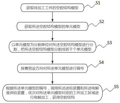
[0065] like Figure 1-12 As shown, an electrolytic machining method, which involves calling a feeding device 1 and an electrolyte supply device 2 to process a three-dimensional cavity, includes the following steps:

[0066] S1. Obtain a cavity structure model of the workpiece to be processed. The workpiece 3 to be processed can be a sphere, a cube, a cylinder, etc.; wherein the outer surface of the workpiece 3 to be processed is a smooth surface or a smooth surface formed by preliminary processing, so as to ensure that the adsorption disk 12 on the adsorption part 8 can be Under the acti...


PUM


Abstract

The invention discloses an electrolytic machining method, a terminal and a storage medium, the method relates to calling a feeding device and an electrolyte supply device to machine a three-dimensional cavity, and the method comprises the steps that a cavity structure model of a workpiece to be machined is obtained; obtaining a unit model of the cavity structure model; segmenting the cavity structure model by taking a unit model as a segmentation unit, and segmenting the cavity structure model into a plurality of unit models; numbering the unit models according to a preset direction; according to the serial numbers of the unit models, the feeding device and the electrolyte supply device are called, electrolytic machining is conducted on workpiece machining areas corresponding to the unit models in sequence, and a cavity structure is obtained; a three-dimensional cavity structure is divided into unit model structures, a feeding device and an electrolyte device are called, a sealed machining area is formed at the machining end and the machining position of a cathode, electrolysis products and waste gas are recycled, and the environment is protected; and meanwhile, the machining efficiency is improved, and the protection effect on the cathode is improved.

Description

technical field [0001] The invention relates to the technical field of electrolytic machining, in particular to an electrolytic machining method, a terminal and a storage medium. Background technique [0002] Electrolytic machining is widely used in the processing of various materials because it is not limited by the hardness and toughness of the processed material, and can obtain better surface processing quality. [0003] In electrolytic machining, when the workpiece needs to be processed into a porous structure, single electrode assemblies are used to process one by one, which is inefficient; multiple electrode assemblies are used for simultaneous processing, which has the problem of inconvenient control; at the same time, gas will be generated during electrolytic machining. , such as Cl2, Br2 and other harmful gases, if not collected and centrally treated, it will pollute the environment and affect the physical and mental health of the staff; with the increase of the dep...

Claims


Application Information

Patent Timeline
Patent Type & Authority Applications(China)
IPC IPC(8): B23H3/00B23H3/10
CPCB23H3/00B23H3/10
Inventor 刘宇
Owner 刘宇
Why Eureka
Try Eureka