Laser welding machine head with automatic wire feeding function

A laser welding and laser head technology, applied in laser welding equipment, welding equipment, manufacturing tools, etc., can solve problems such as empty welding, unable to monitor wire feeding, and affect welding effect

Pending Publication Date: 2022-07-22
深圳市恒川激光技术有限公司
View PDF0 Cites 1 Cited by
  • Summary
  • Abstract
  • Description
  • Claims
  • Application Information

AI Technical Summary

Problems solved by technology

[0005] Aiming at the deficiencies of the prior art, the present invention provides a laser welding machine head with automatic wire feeding function, which has the advantages of automatic high-precision monitoring of welding wire delivery, and the advantages of adjusting the wire feeding speed according to the welding wire delivery, solving the problem of inability to Monitoring the wire feeding situation will affect the welding effect and even cause the problem of empty welding

Method used


Image

  • Laser welding machine head with automatic wire feeding function
  • Laser welding machine head with automatic wire feeding function
  • Laser welding machine head with automatic wire feeding function

Examples


Embodiment 1

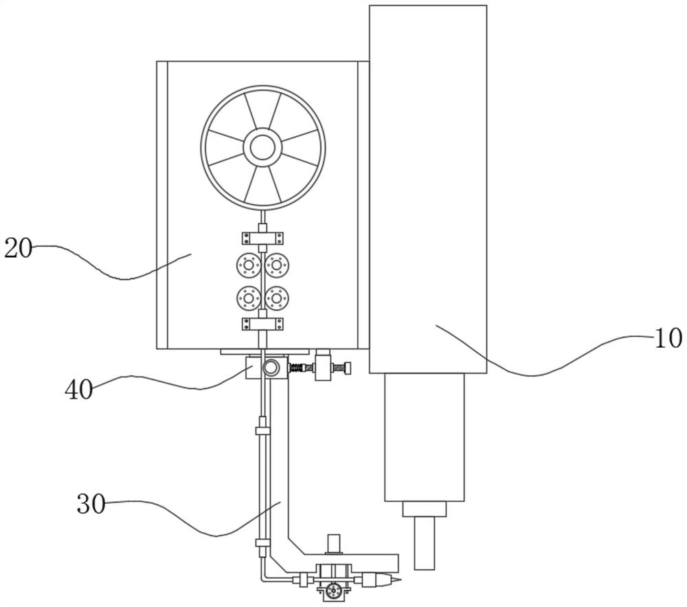
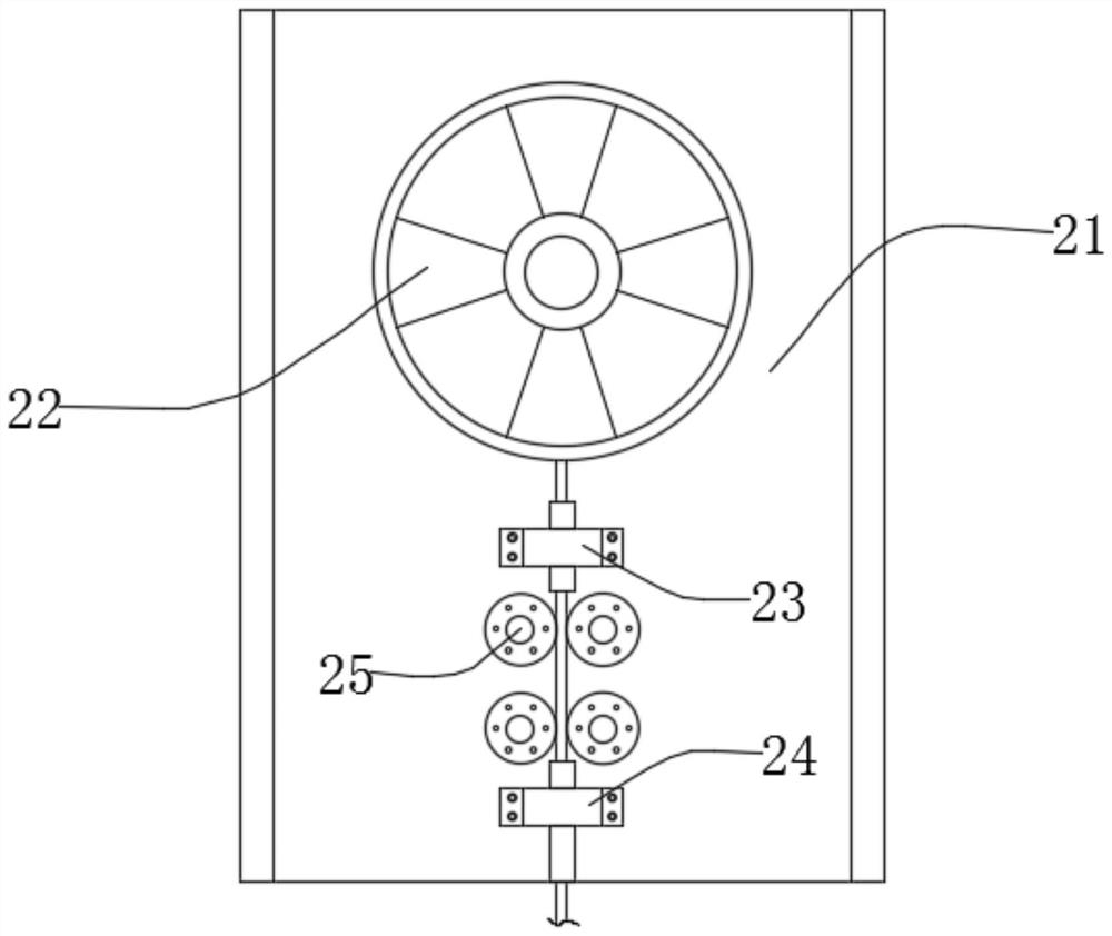
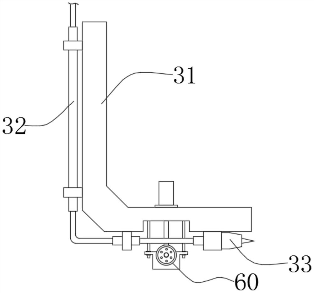
[0044] A laser welding head with automatic wire feeding function, comprising a laser head 10, a wire feeding assembly 20 and a supporting assembly 30 fixed on the wire feeding assembly 20, the wire feeding assembly 20 comprises a supporting plate 21, and the outer side wall of the supporting plate 21 is A wire feeding wheel 22 is rotatably connected, the wire feeding end of the wire feeding wheel 22 is provided with a limit seat 23 and a limit seat 2 24, and a wire feeding wheel 25 is arranged between the limit seat 1 23 and the limit seat 2 24, and the feeding wheel 25 is provided. There are four wire feeders 25 in total. The input ends of the four wire feeders 25 are all connected to the driving equipment, and the four wire feeders 25 are symmetrically distributed in a group of two. The support assembly 30 includes a bracket 31. The outer side wall is fixedly connected with a wire feeding tube 32 and a wire outlet 33, and the bottom of the wire feeding assembly 20 is fixedly ...

Embodiment 2

[0049] On the basis of the first embodiment, the function of auxiliary wire feeding is added.

[0050] An auxiliary wire feeding assembly 60 for auxiliary wire feeding is also installed on the outer side wall of the support assembly 30. The auxiliary wire feeding assembly 60 includes a wire feeding frame 61 and a hydraulic cylinder 62 installed on the outer side wall of the supporting assembly 30. The telescopic end of the hydraulic cylinder 62 is fixed A wire feeding frame 61 is connected, and an auxiliary wire feeding wheel 64 is rotatably connected to the outer side wall of the wire feeding frame 61. A servo motor 65 is installed on one side of the wire feeding frame 61, and the input shaft of the auxiliary wire feeding wheel 64 is connected with the output of the servo motor 65. The shaft is fixedly connected, and the outer side wall of the wire feeder 61 is slidably connected with two symmetrically distributed limit polished rods 63 , and one end of the limit polished rods...


PUM


Abstract

The invention relates to the technical field of laser welding, and discloses a laser welding head with an automatic wire feeding function, which comprises a laser head, a wire feeding assembly and a support assembly fixed on the wire feeding assembly, the bottom of the wire feeding assembly is fixedly connected with a detection assembly, and the detection assembly comprises a detection plate. The top of the detection plate is in sliding connection with the wire feeding assembly through a sliding rail, and the outer side wall of the detection plate is rotationally connected with a detection wheel; during wire feeding, a welding wire can drive the detection wheel to rotate, so that the rotary encoder on the detection wheel can detect the rotating speed of the detection wheel, and when the rotating speed is lower than or higher than a preset value, the rotary encoder can control the driving equipment through the single chip microcomputer, so that the wire feeding wheel on the driving equipment can adapt to the wire feeding speed according to the detected value; in this way, the wire feeding condition can be automatically monitored, when the wire feeding speed is too fast or too slow or the wire clamping phenomenon occurs, the wire feeding speed can be automatically adjusted, a user is reminded, and maintenance is conducted in time.

Description

technical field [0001] The invention relates to the technical field of laser welding, in particular to a laser welding machine head with automatic wire feeding function. Background technique [0002] Laser welding is an efficient and precise welding method that uses a high-energy-density laser beam as a heat source. Laser welding is one of the important aspects of the application of laser material processing technology. Laser welding can be realized by continuous or pulsed laser beam. The principle of laser welding can be divided into heat conduction welding and laser deep penetration welding. When the power density of laser welding is less than 104W / cm2 ~ 105W / cm2, the laser welding method is thermal conduction welding, and the penetration depth is shallow and the welding speed is slow. When the power density of laser welding is greater than 105W / cm2 ~ 107W / cm2, the metal surface is concave into "holes" under the action of heat, forming deep penetration welding, which has...

Claims


Application Information

Patent Timeline
Patent Type & Authority Applications(China)
IPC IPC(8): B23K26/21B23K26/70
CPCB23K26/21B23K26/702
Inventor 罗序庆
Owner 深圳市恒川激光技术有限公司
Why Eureka
Try Eureka