Roller line and workstation for hub deburring

A technology of deburring and roller table, which is applied in the field of surface treatment of parts, can solve the problems affecting the precision of deburring processing of hub workpieces, affecting the accuracy of clamping and positioning of hub workpieces, and reducing processing efficiency, etc., to achieve clamping and fixing stability, The effect of reducing vibration and improving the positioning accuracy of clamping

Pending Publication Date: 2022-07-22
浙江今飞机械有限公司 +2
View PDF0 Cites 0 Cited by
  • Summary
  • Abstract
  • Description
  • Claims
  • Application Information

AI Technical Summary

Problems solved by technology

[0003] In the existing wheel hub workpiece deburring process, usually the wheel hub workpiece cannot be directly deburred on the assembly line, thereby reducing the processing efficiency, and because there will be gaps between the transmission of the clamping blocks during the moving process, in the After the fixture fixes the hub workpiece, the clamp block will move due to the transmission gap of the fixture, so that the clamped hub workpiece may become loose, which will affect the accuracy of the clamping and positioning of the hub workpiece, and then affect the accuracy of the deburring process of the hub workpiece

Method used


Image

  • Roller line and workstation for hub deburring
  • Roller line and workstation for hub deburring
  • Roller line and workstation for hub deburring

Examples


Embodiment 1

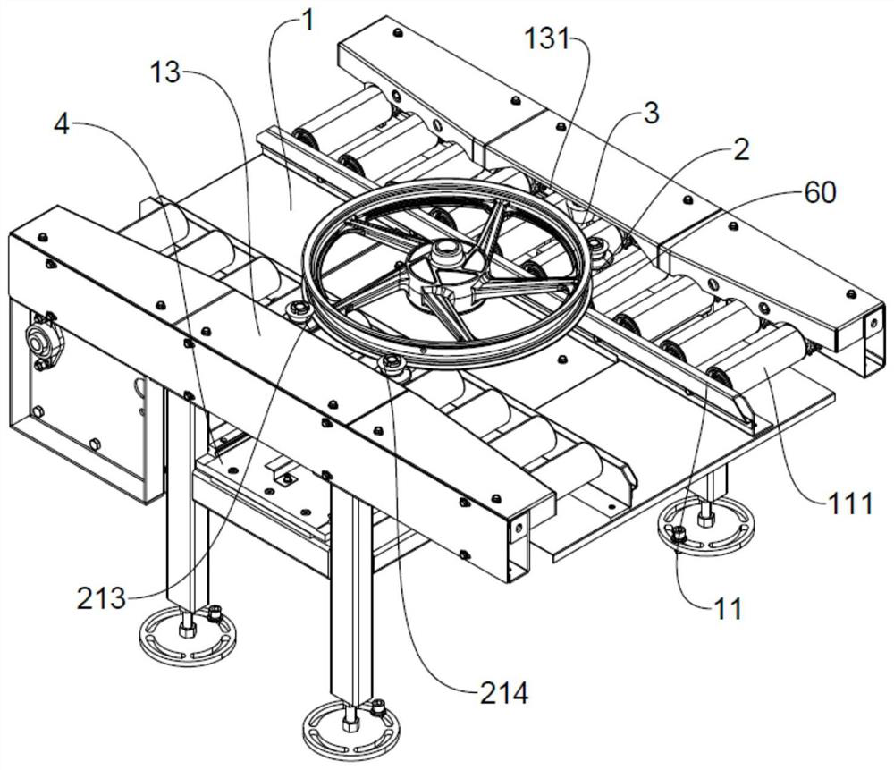
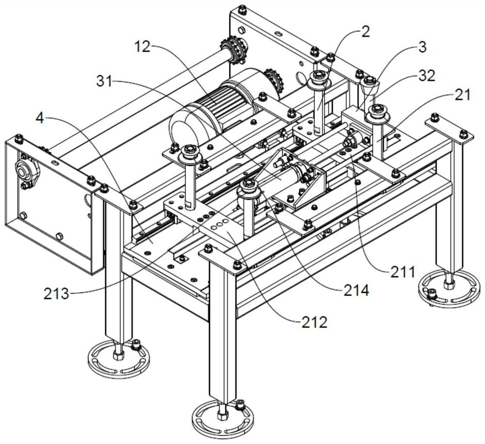
[0035] Depend on Figure 1-5 As shown, a roller table line for deburring a wheel hub includes a first support plate 1, a clamping mechanism 2 for clamping and positioning the workpiece of the hub, and a tensioning mechanism 3 for eliminating the transmission gap of the clamping mechanism 2, The first support plate 1 is provided with a roller table 11 , and a first driver 12 for driving the rollers 111 of the roller table 11 to rotate is fixed at the first support plate 1 .

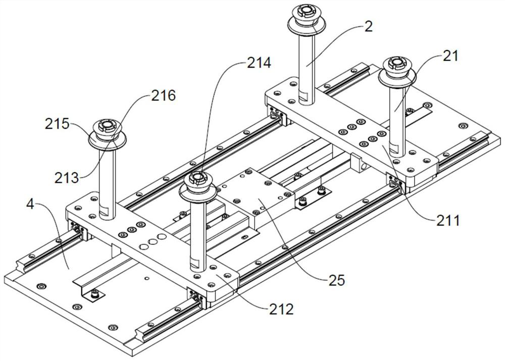
[0036] Depend on Figure 3-5 As shown, the clamping mechanism 2 includes a clamping block 21 located between the adjacent rollers 111 of the roller table 11 and a second driver 22 for driving the clamping block 21 to move in the left-right direction. The clamping block 21 includes a first clamping block 211 and a second driving block 22. Two clamping blocks 212 , a second supporting plate 4 provided below the first supporting plate 1 , the first clamping block 211 is slidably fitted on the right side of t...

Embodiment 2

[0052] Depend on Figure 1-5 As shown, a gear 23 is provided between the first clamping block 211 and the second clamping block 212, the gear 23 is rotatably arranged above the first support plate 1, and both the first clamping block 211 and the second clamping block 212 are provided with the gear 23 In the meshed rack structure 24 , the gear rotates under the action of the second driver 22 , and drives the first clamping block 211 and the second clamping block 212 to translate simultaneously through the rack structure meshing with the gear 23 .

[0053] The second driver 22 of the channel drives the gear 23 to rotate, so that the rack structure 24 moves toward each other in the left-right direction, and makes the first clamping block 211 move to the left and the second clamping block 212 to the right. The part 60 is clamped and positioned.


PUM


Abstract

The invention relates to the field of part surface treatment, in particular to a roller line and a workstation for hub deburring. The clamping mechanism is used for clamping and positioning a hub workpiece, the tensioning mechanism is used for eliminating a transmission gap of the clamping mechanism, a roller way is arranged on the first supporting plate, and a first driver used for driving rollers of the roller way to rotate is fixed to the first supporting plate. The hub deburring device has the advantages that a hub workpiece can be directly deburred on the roller way; the error of a transmission gap of the clamp can be eliminated, and the hub workpiece is prevented from loosening after being clamped; the clamping block body can clamp a hub workpiece more stably, and vibration of the hub workpiece in the machining process is reduced; through the visual sensor, different machining parts can be judged, and the path of the deburring head is automatically adjusted; and the position of the visual sensor can be adjusted, so that the accuracy of the position of the visual sensor is ensured.

Description

technical field [0001] The invention relates to the field of surface treatment of parts, in particular to a roller table line and a workstation for deburring a wheel hub. Background technique [0002] Some burrs on mechanical parts are caused by plastic deformation during the cutting process; some are burrs from casting, die forging, etc., and some are residual materials from welding and extrusion. With the improvement of industrialization and automation, in the field of mechanical processing, especially in the fields of aviation, aerospace, and instrumentation, the requirements for manufacturing precision of mechanical parts and the miniaturization of mechanism design are increasing. General attention, and began to study the burr generation mechanism and removal methods. [0003] In the existing process of deburring the hub workpiece, it is usually not possible to directly deburr the hub workpiece on the assembly line, thereby reducing the processing efficiency. After the...

Claims


Application Information

Patent Timeline
Patent Type & Authority Applications(China)
IPC IPC(8): B24B9/04B24B27/00B24B41/06B24B47/00B24B49/12B24B51/00
CPCB24B9/04B24B27/0023B24B41/06B24B47/00B24B49/12B24B51/00
Inventor 郑啸天王伟勇童诚昊童丽芳
Owner 浙江今飞机械有限公司
Why Eureka
Try Eureka