Eureka AIR delivers breakthrough ideas for toughest innovation challenges, trusted by R&D personnel around the world.

Heat supply protection control method and device for cogeneration unit

A heat and power cogeneration unit, protection and control technology, applied in steam engine installations, heating methods, household heating, etc., can solve the problem of thrust pad wear and burn, steam turbine axial thrust and changes in the pressure ratio of high and medium pressure cylinders, affecting the power supply of the unit Thermal stability and safety issues, to achieve the effect of enhancing safety and reliability, and improving deep peak-shaving capabilities

Pending Publication Date: 2022-07-22
NORTH CHINA ELECTRICAL POWER RES INST +1
View PDF0 Cites 0 Cited by
  • Summary
  • Abstract
  • Description
  • Claims
  • Application Information

AI Technical Summary

Problems solved by technology

[0003] The cogeneration unit will frequently switch between condensate extraction and bypass heating during deep peak regulation, and the high and low bypass steam parameters in the bypass heating state are higher than those when the steam turbine is normally started and stopped, which deteriorates the high and low bypass conditions. The working environment of the valve, and because the high-low bypass is connected with the steam turbine in parallel and the steam intake parameters change frequently, resulting in frequent changes in the axial thrust of the steam turbine and the pressure ratio of the high and medium pressure cylinders. Control and limit. In extreme cases, the axial thrust of the unit, the temperature of the thrust tile and the pressure ratio of the high and medium pressure cylinders exceed the limit, and the thrust tile will be worn out and burned, and the final blade of the high and medium pressure rotor will be damaged, which will affect the heat supply of the unit under deep peak regulation. Stability and Security

Method used

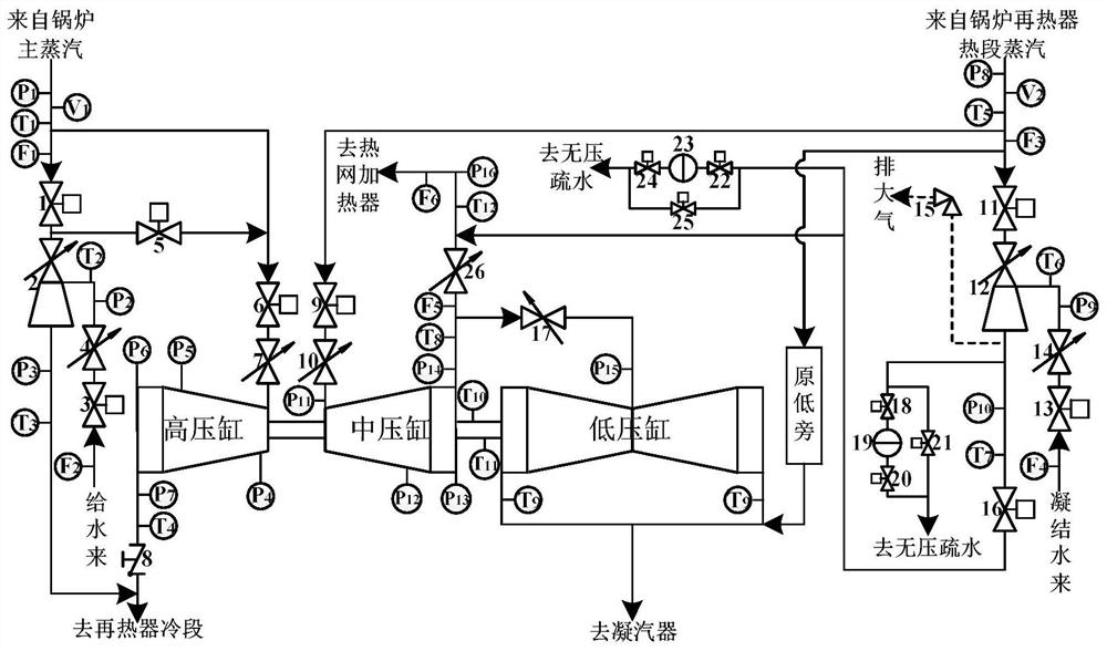
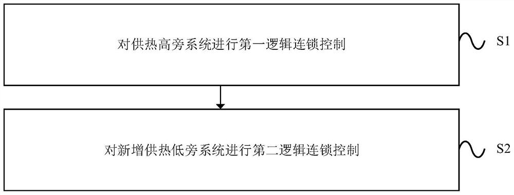
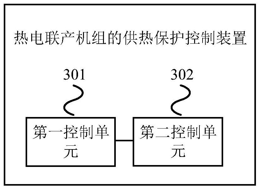

Image

  • Heat supply protection control method and device for cogeneration unit
  • Heat supply protection control method and device for cogeneration unit
  • Heat supply protection control method and device for cogeneration unit

Examples


Embodiment Construction

[0137]In order to make the purposes, technical solutions and advantages of the embodiments of the present invention more clearly understood, the embodiments of the present invention will be further described in detail below with reference to the accompanying drawings. Here, the exemplary embodiments of the present invention and their descriptions are used to explain the present invention, but not to limit the present invention. It should be noted that, the embodiments in the present application and the features in the embodiments may be arbitrarily combined with each other if there is no conflict.

[0138] Key words, key term definitions and abbreviations in the embodiments of the present invention are described as follows:

[0139] Key words: combined heat and power; steam turbine; deep peak shaving; flexibility transformation; thermo-decoupling; bypass heating; protection control.

[0140] Definition of key terms:

[0141] Pure condensing condition: For the cogeneration un...


PUM


Abstract

The invention provides a heat supply protection control method and device for a combined heat and power generation unit. The heat supply protection control method comprises the steps that first logic interlocking control is conducted on a heat supply high-side system, and second logic interlocking control is conducted on a newly-added heat supply low-side system. The device executes the method. According to the heat supply protection control method and device of the combined heat and power generation unit, it can be guaranteed that relevant steam turbine body and high and low bypass heat supply parameters are located in a safe operation space in the bypass heat supply state, the safety and reliability of the unit in the bypass heat supply state are improved, and the continuous response speed of the unit to heat and power load changes is increased; and the deep peak regulation capacity of the unit can be improved.

Description

technical field [0001] The invention relates to the technical field of automatic control, in particular to a heating protection control method and device for a cogeneration unit. Background technique [0002] Bypass heating technology is an important thermal and electrolytic coupling method. This method requires less unit transformation and lower investment, and can greatly improve the deep peak shaving capability of cogeneration units. [0003] During deep peak regulation, the cogeneration unit will frequently switch between extraction and condensation and bypass heating, and in the bypass heating state, the inlet steam parameters of the high and low side are higher than that of the normal start and stop of the steam turbine, which worsens the difference between the high and low side. The working environment of the valve, at the same time, due to the parallel inlet of the steam turbine with the high and low sides and the frequent changes of the steam inlet parameters, the a...

Claims


Application Information

Patent Timeline
Patent Type & Authority Applications(China)
IPC IPC(8): F01K11/02F01D17/10F24D1/02F24D1/08F24D19/10
CPCF01K11/02F01D17/10F24D1/02F24D1/08F24D19/1003
Inventor 司派友王维萌刘磊王斌刘绍杰王超明曹欢刘晓东董伟王德鹏左川刘双白梅隆宋亚军
Owner NORTH CHINA ELECTRICAL POWER RES INST
Why Eureka
Eureka Blog
Learn More