Multifunctional operation integrated valve, control module, hydraulic system and forcible entry robot

A hydraulic system and integrated valve technology, applied in the hydraulic application field, can solve the problems of large system matching power loss, devices that cannot work at the same time, and high cost, and achieve the effects of good scalability, simple structure, and easy operation

Pending Publication Date: 2022-07-22
JIANGSU XCMG CONSTR MASCH RES INST LTD
View PDF0 Cites 0 Cited by
  • Summary
  • Abstract
  • Description
  • Claims
  • Application Information

AI Technical Summary

Problems solved by technology

[0004] The telescopic rotation of the front clamp device adopts the scheme of closed pump + overflow valve + electric control switch multi-way valve. Disadvantages: the cost of closed pump is high, and the domestic small flow multi-way directional valve has no electric control and no floating position; The road reversing valve cannot meet the speed regulation requirements of the working mechanism; the mechanical arm and forklift are realized by the scheme of quantitative gear pump + overflow valve + electric proportional plate reversing valve. Disadvantage: share one gear pump, and different devices work through two The three-way reversing valve is switched, and the device cannot work at the same time; the pressure of the gear pump is low, and the pump displacement cannot be adjusted according to the load, which cannot meet the functional requirements of current multi-tools; the electric proportional plate reversing valve cannot realize flow sharing and compounding action, the cost is relatively high, and the system matching power loss is large

Method used


Image

  • Multifunctional operation integrated valve, control module, hydraulic system and forcible entry robot
  • Multifunctional operation integrated valve, control module, hydraulic system and forcible entry robot
  • Multifunctional operation integrated valve, control module, hydraulic system and forcible entry robot

Examples


Embodiment Construction

[0049] The technical solutions in the embodiments of the present invention will be clearly and completely described below with reference to the accompanying drawings in the embodiments of the present invention. Obviously, the described embodiments are only a part of the embodiments of the present invention, but not all of the embodiments. Based on the embodiments of the present invention, all other embodiments obtained by those of ordinary skill in the art without creative efforts shall fall within the protection scope of the present invention.

[0050] The relative arrangement of the components and steps, the numerical expressions and numerical values ​​set forth in these embodiments do not limit the scope of the invention unless specifically stated otherwise. Meanwhile, it should be understood that, for the convenience of description, the dimensions of various parts shown in the accompanying drawings are not drawn in an actual proportional relationship. Techniques, methods, ...


PUM


Abstract

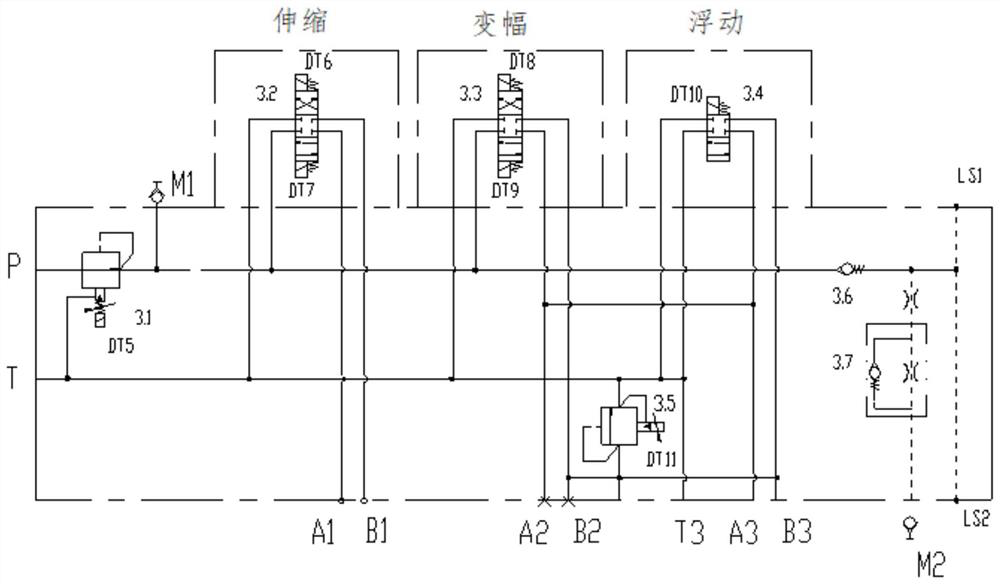
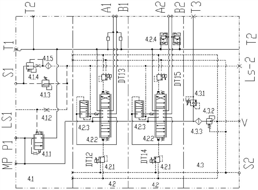
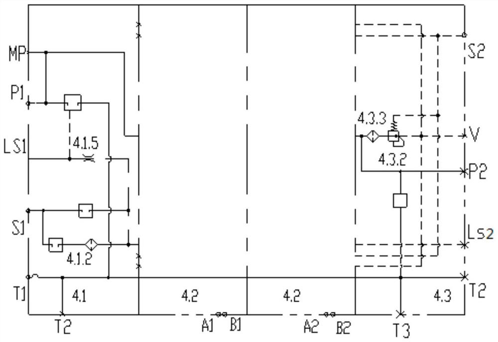
The invention relates to the technical field of hydraulic application, and discloses a multifunctional operation integrated valve, a control module, a hydraulic system and a forcible entry robot, which comprises a switch pressure reducing valve, a telescopic electric control switch valve, a variable amplitude electric control switch valve, a floating electric control switch valve and an electric control proportional overflow valve, the telescopic electric control switch valve, the variable-amplitude electric control switch valve and the floating electric control switch valve are arranged on the valve block in an overlapped mode. An inlet of the switch pressure reducing valve is connected with an outlet of a variable displacement piston pump in the hydraulic system; one outlet of the switch pressure reducing valve is respectively communicated with main oil inlets P of the telescopic electric control switch valve and the variable amplitude electric control switch valve, and the other outlet of the switch pressure reducing valve is communicated with the oil return channel in the valve block; the control module comprises a load-sensitive control valve group and an integrated valve. The multifunctional robot has the beneficial effects that multiple combined functions such as forcible entry, excavation, carrying and hoisting can be achieved by carrying multiple operation tools, modular rapid disassembly and assembly can be achieved, and the multifunctional robot is suitable for different operation scenes.

Description

technical field [0001] The invention relates to the technical field of hydraulic applications, relates to a multifunctional operation integrated valve, a control module, a hydraulic system and a demolition robot, in particular to a bulldozer clamp integrated valve, a bulldozer clamp operation control module and a demolition robot. Hydraulic system. Background technique [0002] The demolition rescue robot has the function of portable terminal operation, and can be equipped with a variety of working tools to meet various combined functions such as demolition, excavation, handling, and lifting. The walking of the dismantling robot, the work of the mechanical arm and the work of the attachment require hydraulic drive. The hydraulic drive technology involves a large number of control components, and its integration with valves, pumps and actuators determines that the hydraulic drive needs one for a variety of equipment properties. In the integrated environment, it is necessary ...

Claims


Application Information

Patent Timeline
Patent Type & Authority Applications(China)
IPC IPC(8): F15B21/08F15B11/16F15B13/06F15B19/00F15B21/041F15B21/0423B25J11/00
CPCF15B21/087F15B11/161F15B13/06F15B19/00F15B21/041F15B21/0423B25J11/00
Inventor 高荣梁康赵戈
Owner JIANGSU XCMG CONSTR MASCH RES INST LTD
Why Eureka
Try Eureka