Integrated optical element

A technology for integrating optics and optical components, applied in the field of optical fiber communication and fiber lasers, can solve the problems of large space occupation, complicated operation, large optical loss, etc., and achieve the effect of reducing space occupation, simplifying operation process, and reducing space occupation

Pending Publication Date: 2022-07-22
深圳市欧凌镭射科技有限公司
View PDF0 Cites 0 Cited by
  • Summary
  • Abstract
  • Description
  • Claims
  • Application Information

AI Technical Summary

Problems solved by technology

[0008] In view of the above problems, the present application provides an integrated optical component, which at least solves the problems of cumbersome operation, large space o

Method used


Image

  • Integrated optical element
  • Integrated optical element
  • Integrated optical element

Examples


Embodiment 1

[0044] The embodiment of the present application provides an integrated optical element, which integrates the functions of a wavelength division multiplexer, an isolator, and a mode field adapter. While the functions are integrated, the occupation of workpieces is reduced and the cost is reduced.

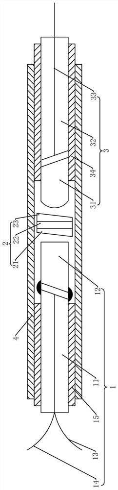
[0045] refer to figure 1 , the integrated optical element provided in this embodiment includes a first optical component 1 , an isolator core 2 and a second optical component 3 arranged in sequence.

[0046] The first optical assembly 1 includes a first capillary 11 and a first demultiplexing lens 12 arranged in sequence, wherein the first demultiplexing lens 12 is arranged between the first capillary 11 and the isolator core 2, and the first demultiplexing lens 12 faces the isolation One end of the core 2 is coated with a WDM film, and the WDM film is a wavelength division multiplexing film, which is used to divide or combine light of two wavelengths.

[0047] The first optical as...

Embodiment 2

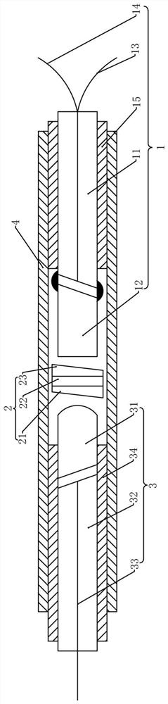
[0082] refer to figure 2 On the basis of the first embodiment, this embodiment provides another optical path for integrating optical elements. In this embodiment, the first signal light is input from the second optical component 3, passes through the isolator core 2 and then passes through the first optical component. The output of the component 1, specifically, the first signal light is transmitted from the third optical fiber 33 into the second optical component 3, enters the C lens 31 through the second capillary 32 and the flat surface of the C lens 31, and is collimated by the convex surface of the C lens 31. Straight out, after the isolator core 2, it enters the end face of the first wave splitting lens 12 coated with the WDM film, and is transmitted to the first capillary 11 through the first wave splitting lens 12, and the signal light of the first wavelength is transmitted from the first wave. Fiber 13 output.

[0083] At the same time, the second signal light is in...

Embodiment 3

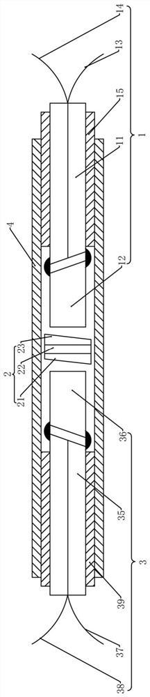
[0086] refer to image 3 , on the basis of the first embodiment, the second optical component 3 has the same structure as the first optical component 1 , and is symmetrically arranged with respect to the isolator core 2 .

[0087] The first optical assembly 1 includes a first capillary 11 and a first demultiplexing lens 12 arranged in sequence, wherein the first demultiplexing lens 12 is arranged between the first capillary 11 and the isolator core 2, and the first demultiplexing lens 12 faces the isolation One end of the core 2 is coated with a WDM film.

[0088] The first optical assembly 1 further includes a first optical fiber 13 and a second optical fiber 14 . One ends of the first optical fiber 13 and the second optical fiber 14 pass through the first capillary tube 11 and extend outside the first capillary tube 11 , and the other end of the first optical fiber 13 . One end is connected to the end face of the first capillary 11 facing the first demultiplexing lens 12, t...


PUM


Abstract

The invention is suitable for the technical field of optical fiber communication and optical fiber lasers, and provides an integrated optical element which comprises a first optical assembly, an isolator core and a second optical assembly which are arranged in sequence. The first optical assembly comprises a first capillary tube, a first wave splitting lens, a first optical fiber and a second optical fiber, the first optical fiber and the second optical fiber penetrate through the first capillary tube, and the first wave splitting lens is arranged between the first capillary tube and the isolator core; one end of the first optical fiber and one end of the second optical fiber are packaged in the first capillary tube, the other end of the first optical fiber and the other end of the second optical fiber extend out of the first capillary tube, and the end, facing the isolator core, of the first wave division lens is plated with a WDM film; the wavelength division multiplexer is simple in structure and easy to operate, integrates the functions of the wavelength division multiplexer, the isolator and the mode field adapter, reduces the occupied space, reduces the cost, and is high in practicability.

Description

technical field [0001] The present application relates to the technical fields of optical fiber communication and optical fiber lasers, and in particular, to an integrated optical element. Background technique [0002] In the field of optical fiber communication or fiber laser, optical isolators, wavelength division multiplexers (WDM), mode field adapters and other devices are often used. The optical isolator is a non-reciprocal device, its function is to make the light transmitted in the forward direction pass through with a small insertion loss, while the light transmitted in the reverse direction is isolated, which plays the role of protecting the system and improving the system. output stability. A wavelength division multiplexer (WDM) is a device that can combine or split signals of different wavelengths. Mode field adapters are used to connect fibers of different core diameters to transmit with lower loss. [0003] The current general scheme of the above devices is ...

Claims


Application Information

Patent Timeline
IPC IPC(8): G02B6/27G02B6/293G02B6/32
CPCG02B6/2746G02B6/2938G02B6/32
Inventor 吴朝辉李成宽
Owner 深圳市欧凌镭射科技有限公司
Why Eureka
Try Eureka