Silicon controlled rectifier electrostatic discharge protection structure

A technology of electrostatic discharge protection and thyristor, which is applied in the direction of circuits, electrical components, electric solid devices, etc., can solve the problems of poor electrostatic discharge protection effect and poor electrostatic discharge discharge ability, and achieve short current path and enhanced discharge capability, the effect of small on-resistance

Active Publication Date: 2022-07-22
MICROTERA SEMICON (GUANGZHOU) CO LTD
View PDF5 Cites 1 Cited by
  • Summary
  • Abstract
  • Description
  • Claims
  • Application Information

AI Technical Summary

Problems solved by technology

[0003] The invention provides a thyristor electrostatic discharge protection structure to solve the technical problem that the existing thyristor electrostatic discharge protection structure has poor electrostatic discharge discharge ability, resulting in poor electrostatic discharge protection effect

Method used


Image

  • Silicon controlled rectifier electrostatic discharge protection structure
  • Silicon controlled rectifier electrostatic discharge protection structure
  • Silicon controlled rectifier electrostatic discharge protection structure

Examples


Embodiment Construction

[0018] The technical solutions in the embodiments of the present application will be clearly and completely described below with reference to the drawings in the embodiments of the present application. Obviously, the described embodiments are only a part of the embodiments of the present application, rather than all the embodiments. Based on the embodiments in this application, all other embodiments obtained by those of ordinary skill in the art without creative efforts shall fall within the protection scope of this application.

[0019] In the description of this application, it should be understood that the terms "first" and "second" are only used for description purposes, and cannot be interpreted as indicating or implying relative importance or implicitly indicating the number of indicated technical features. Thus, a feature defined as "first" or "second" may expressly or implicitly include one or more of that feature. In the description of this application, unless stated ...


PUM


Abstract

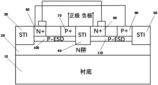
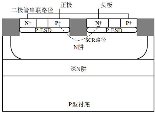
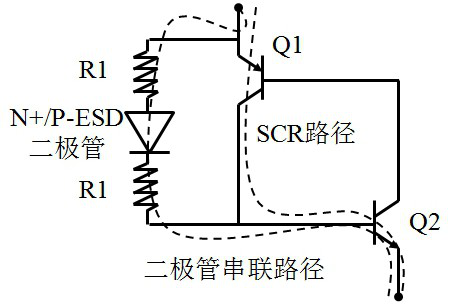
The invention discloses a silicon controlled rectifier electrostatic discharge protection structure which comprises a substrate, an N well, a first isolation groove, a second isolation groove, a third isolation groove, a first N + injection region, a first P + injection region, a second N + injection region, a second P + injection region, a first ESD injection layer and a second ESD injection layer. The N well is arranged in the surface area of the substrate; the N well is sequentially provided with a first isolation groove, a first ESD injection layer, a second isolation groove, a second ESD injection layer and a third isolation groove from one end to the other end; two sides of the first ESD injection layer are respectively connected with the first isolation groove and the second isolation groove, and two sides of the second ESD injection layer are respectively connected with the second isolation groove and the third isolation groove; a first N + injection region and a first P + injection region are arranged on the surface of the first ESD injection layer, and a second N + injection region and a second P + injection region are arranged on the surface of the second ESD injection layer. According to the embodiment of the invention, the electrostatic discharge protection effect can be effectively improved.

Description

technical field [0001] The invention relates to the technical field of integrated circuits, in particular to a thyristor electrostatic discharge protection structure. Background technique [0002] Electrostatic discharge (ESD) of chips is becoming more and more important as microelectronic devices move toward size reduction and functional integration. On the one hand, the gate dielectric and isolation of small-sized devices are thinner, which leads to a weakening of the device's ability to withstand static electricity, thereby narrowing the window for ESD device design; on the other hand, more and more modules are integrated on the same silicon substrate, resulting in chip There is an increasing risk of being exposed to electrostatic discharge. The electrostatic discharge discharge capability of the existing SCR electrostatic discharge protection structure is poor, resulting in poor electrostatic discharge protection effect. SUMMARY OF THE INVENTION [0003] The inventio...

Claims


Application Information

Patent Timeline
IPC IPC(8): H01L27/02
CPCH01L27/0262H01L27/0255
Inventor 刘尧史林森关宇轩梁国豪陈达伟刘森
Owner MICROTERA SEMICON (GUANGZHOU) CO LTD
Why Eureka
Try Eureka