Direct current charging and discharging system and method capable of actively adjusting power

A power and active technology, applied in parallel operation of DC power supply, secondary battery charging/discharging, current collectors, etc., can solve the problem that energy storage capacity has not been optimally dispatched, energy storage devices have not received sufficient attention, and flexible energy use potential It needs to be further explored and other issues to achieve the effect of promoting power demand response, ensuring stable operation and wide coverage

Pending Publication Date: 2022-07-22
TSINGHUA UNIV
View PDF0 Cites 0 Cited by
  • Summary
  • Abstract
  • Description
  • Claims
  • Application Information

AI Technical Summary

Problems solved by technology

Based on this, a large number of existing technologies have proposed active power regulation control methods for loads in DC microgrids. However, a large number of energy storage devices in DC microgrids have not yet received sufficient attention. Power Active Adjustment Control Method
However, these methods often ignore the state differences of many energy storage devices in the DC microgrid, that is, the impact of their own energy storage capacity parameters on the participating demand response capabilities, such as: the current remaining power of the device, the command charge / discharge allowed by the device power etc.
Therefore, a large amount of energy storage capacity of this type of energy storage device has not yet been optimally dispatched, and the potential of flexible energy utilization on the user side needs to be further explored.

Method used


Image

  • Direct current charging and discharging system and method capable of actively adjusting power
  • Direct current charging and discharging system and method capable of actively adjusting power
  • Direct current charging and discharging system and method capable of actively adjusting power

Examples


Embodiment 1

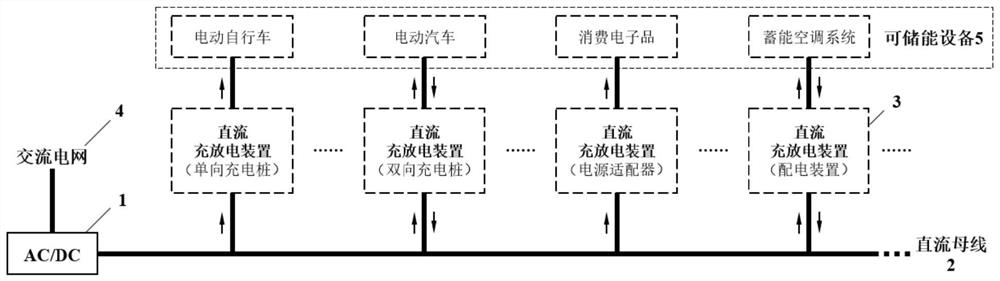
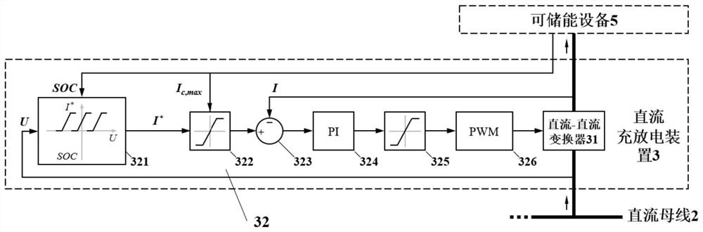
[0060] like figure 1 , figure 2 and Figure 4 As shown, this embodiment provides a DC charging and discharging system whose power can be actively adjusted, including an AC-DC converter 1, a DC bus 2 and a DC charging and discharging device 3, wherein the DC charging and discharging device 3 includes a DC-DC converter 31 and control circuit 32, the DC charging and discharging device 3 can be used as a one-way charging pile, a two-way charging pile, a power adapter and / or a power distribution device.

[0061] The input end of the AC-DC converter 1 is connected to the AC grid 4 , and the output end of the AC-DC converter 1 is connected to the input end of the DC bus 2 . The output end of the DC bus 2 is respectively connected to the first input end of the DC-DC converter 31 and the first input end of the control circuit 32, the second input end of the DC-DC converter 31 is connected to the output end of the control circuit 32, the DC-DC The third input end of the DC converter...

Embodiment 2

[0078] like figure 2 As shown, this embodiment provides a DC charging and discharging method with active power adjustment, including the following steps:

[0079] 1) The control circuit 32 obtains the energy storage capacity parameter of the energy storage device 5 and obtains the voltage U of the DC bus 2 from the DC-DC converter 31 .

[0080] Specifically, the energy storage capability parameters of the energy-storable device 5 include the state of charge SOC of the energy-storable device 5 and the maximum charging current I allowed by the device. c,max and the maximum discharge current I allowed by the device d,max .

[0081] Further, if the energy storage device 5 or the DC charging and discharging device 3 only allows charging and does not allow discharging, such as a one-way charging pile for electric vehicles, a mobile phone that can only be generally charged, etc., the maximum discharge current I allowed by the device is d,max Take 0.

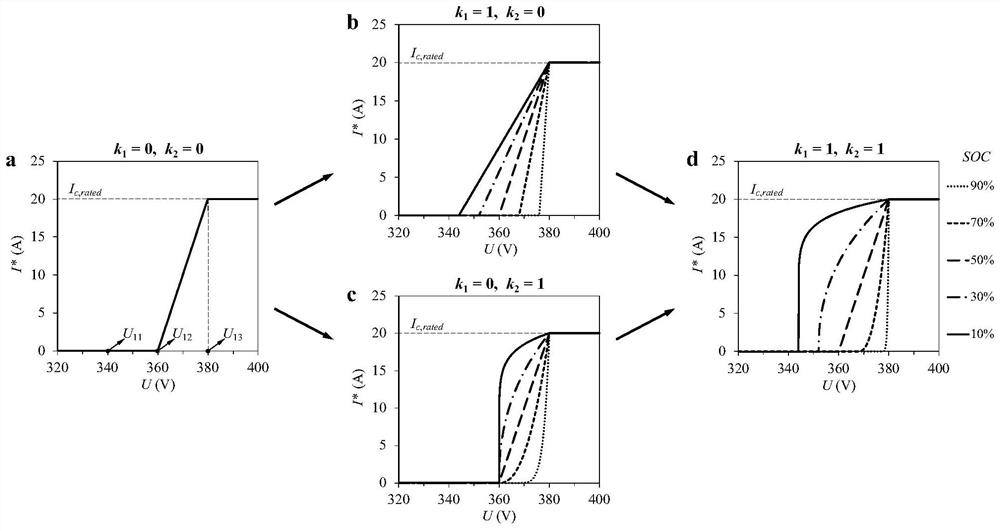
[0082] Specifically, the st...

Embodiment 3

[0111] If the DC-DC converter 31 adopts the constant power control mode, all the current parameters in each step of the above-mentioned Embodiment 2 are replaced with corresponding power parameters, and the principle of the method remains unchanged. Therefore, if Figure 4 As shown, this embodiment provides a DC charging and discharging method with active power adjustment, including the following steps:

[0112] 1) The control circuit 32 obtains the energy storage capacity parameter of the energy storage device 5 and obtains the voltage U of the DC bus 2 from the DC-DC converter 31 .

[0113] In this embodiment, the DC-DC converter 31 adopts a constant power control mode. The voltage U of the DC bus 2 is 375V, and the voltage U of the DC bus 2 can vary from 320V to 400V. The energy storage device 5 is an electric vehicle that supports charging and discharging.

[0114] 2) The command current function calculation module of the control circuit 32 is based on the voltage U of ...


PUM


Abstract

The invention relates to a direct current charging and discharging system and method capable of actively adjusting power, and the system is characterized in that the system comprises an alternating current-direct current converter, a direct current bus and a direct current charging and discharging device, and the direct current charging and discharging device comprises a direct current-direct current converter and a control circuit; the alternating current-direct current converter is used for converting alternating current accessed by an alternating current power grid into direct current; the direct current-direct current converter is used for acquiring direct current bus voltage and energy storage capability parameters of the energy-storable equipment, and controlling charging or discharging of the energy-storable equipment according to PWM waves generated by the control circuit in a constant current control mode or a constant power control mode; the control circuit is used for determining instruction charging/discharging current or power and generating PWM waves according to the voltage of the direct-current bus, the energy storage capacity parameters of the energy storage equipment and the actual operation current or power of the energy storage equipment, and the direct-current micro-grid energy dispatching and operation control method can be widely applied to the field of direct-current micro-grid energy dispatching and operation control.

Description

technical field [0001] The invention relates to the technical field of DC microgrid energy scheduling and operation control, in particular to a DC charging and discharging system and method whose power can be actively adjusted. Background technique [0002] Due to the intermittent and random characteristics of power generation from renewable energy sources such as wind power and photovoltaics, the importance of power demand response has become increasingly prominent, which can provide a guarantee for the safe and stable operation of a zero-carbon power system in the future. At present, China has incorporated demand response into regional power planning, in order to maximize the flexible power regulation resources for user-side loads. [0003] A large number of loads on the user side have considerable energy storage capacity, which can support them for flexible electricity consumption, such as: electric vehicles or electric bicycles connected to charging piles and various con...

Claims


Application Information

Patent Timeline
Patent Type & Authority Applications(China)
IPC IPC(8): H02J7/00H02J7/02H02J1/10H01M10/44
CPCH02J7/0048H02J7/0068H02J7/007H02J7/00712H02J7/02H02J1/10H01M10/441
Inventor 刘效辰江亿刘晓华张涛
Owner TSINGHUA UNIV
Why Eureka
Try Eureka