End mill for cutting optical film and method for manufacturing optical film using same
A technology of optical film and manufacturing method, which is applied in the direction of milling cutters, manufacturing tools, milling machine equipment, etc., to achieve the effect of suppressing burrs
- Summary
- Abstract
- Description
- Claims
- Application Information
AI Technical Summary
Problems solved by technology
Method used
Image
Examples
Embodiment
[0056] Hereinafter, the present invention will be specifically described by way of examples, but the present invention is not limited to these examples. In addition, the evaluation items in the examples are as follows.
[0057](1) Burr
[0058] The cross-section of the workpiece|work (polarizing plate with an adhesive layer attached) obtained in the Example and the comparative example was photographed with a camera. Image analysis was performed on the captured data, the area of the portion corresponding to the burr was calculated, and the evaluation was performed according to the following criteria. Specifically, (i) the captured image is digitized in grayscale (black 0 to white 255), (ii) objects with a brightness of 100 or more and spanning four or more adjacent pixels, and objects with a brightness of 150 or more and Objects spanning 2 to 3 pixels or more adjacent to each other are identified as glitches, and (iii) the glitches are quantified by the sum of the areas (nu...
manufacture example 1
[0062] Production of a polarizing plate with an adhesive layer
[0063] As the polarizer, a long polyvinyl alcohol (PVA)-based resin film containing iodine and uniaxially stretched in the longitudinal direction (MD direction) was used (thickness: 12 μm). An optical functional film (COP film with an antistatic layer) was bonded to one side of the polarizer. In addition, the COP film with an antistatic layer is a film in which an antistatic layer (5 μm) is formed on a cycloolefin (COP) film (25 μm), and the COP film is bonded so that it is on the polarizer side. A surface protection film was bonded to the antistatic layer side of the obtained laminate of polarizer / COP film / antistatic layer. On the other hand, a retardation film (manufactured by Zeon Corporation, Japan, trade name "ZB-12", in-plane retardation Re(550)=50 nm, thickness of 40 μm). Furthermore, a pressure-sensitive adhesive layer (thickness: 20 μm) was formed on the outer side of the retardation film, and a sepa...
Embodiment 1
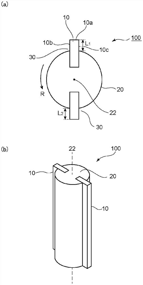
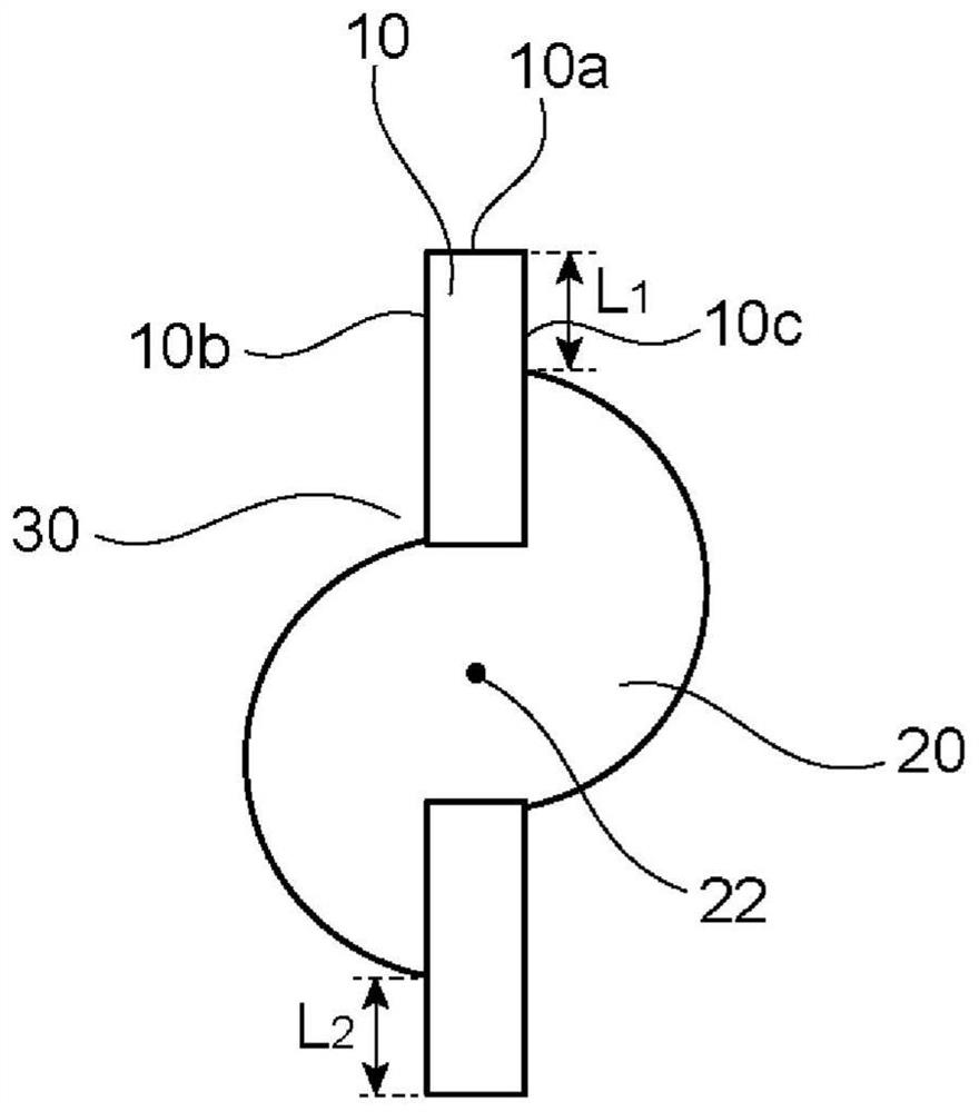
[0065] The polarizing plate with the pressure-sensitive adhesive layer obtained in Production Example 1 was punched out to a size of 5.7 inches (about 140 mm in length and 65 mm in width), and the punched polarizing plates were stacked to form a workpiece (total thickness of about 20 mm). . Polystyrene (PS) sheets were placed on both sides of the obtained workpiece as spacers, and in the state of being held by clamps (jigs), by cutting using an end mill, 4 parts of the outer periphery of the workpiece were cut. A chamfered portion was formed at each corner portion, and a concave portion was formed at the center portion of one of the four outer peripheral surfaces, thereby obtaining the following Figure 7 Non-linear processed polarizer with adhesive layer shown. Here, the number of edges of the end mill is two, the helix angle is 0°, and the outer diameter is 5mm. In addition, the feed speed of the end mill was 1200 mm / min, and the rotation speed was 15000 rpm. Furthermore,...
PUM
| Property | Measurement | Unit |
|---|---|---|
| Outer diameter | aaaaa | aaaaa |
| Length | aaaaa | aaaaa |
Abstract
Description
Claims
Application Information
 - R&D
- Intellectual Property
- Life Sciences
- Materials
- Tech Scout
- Unparalleled Data Quality
- Higher Quality Content
- 60% Fewer Hallucinations
Browse by: Latest US Patents, China's latest patents, Technical Efficacy Thesaurus, Application Domain, Technology Topic, Popular Technical Reports.
© 2025 PatSnap. All rights reserved.Legal|Privacy policy|Modern Slavery Act Transparency Statement|Sitemap|About US| Contact US: help@patsnap.com


