Plastic spraying equipment for processing anti-corrosion reinforcing steel bar
A steel bar processing and anti-corrosion technology, applied in spray booths, spray devices, coatings, etc., can solve the problems of excess paint and uneven spray on the surface of steel bars, and achieve the effect of improving quality, speed, and avoiding unevenness
- Summary
- Abstract
- Description
- Claims
- Application Information
AI Technical Summary
Problems solved by technology
Method used
Image
Examples
Embodiment 1
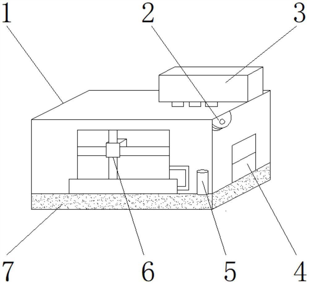
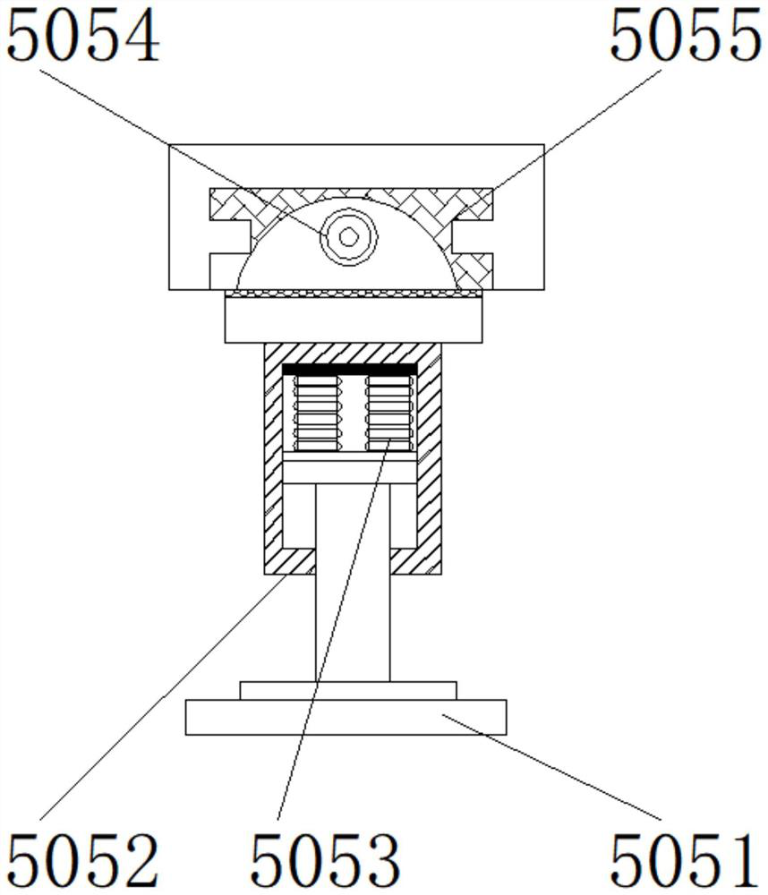
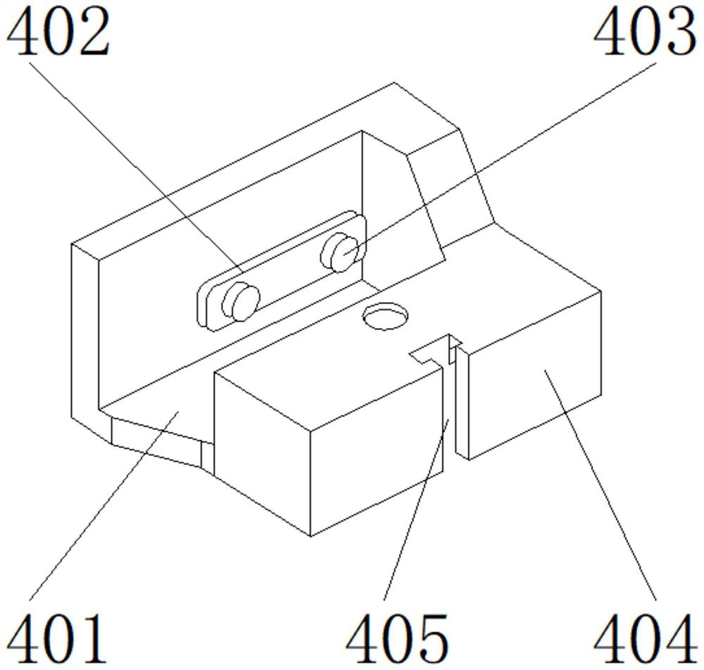
[0029] like Figure 1-6 As shown in the figure, the present invention provides a kind of spraying equipment for anti-corrosion steel bar processing, including a main body 1, the upper end of the main body 1 is provided with a scraping mechanism 3, the interior of the main body 1 is provided with a bracket 6, and one side of the bracket 6 is provided with a conveyor Structure 5, the lower end of the main body 1 is provided with a bottom pad 7, one side of the main body 1 is provided with an air pump 2, and a limiting mechanism 4 is provided below the air pump 2; The limit block 404, the positioning groove 405, the rubber layer 402 is located on one side of the shelf 401, the stitch hole 403 is located on the outer surface of one side of the rubber layer 402; one side of the rubber layer 402 is fixed with one side of the shelf 401 by super glue For connection, one side of the pin hole 403 is fixedly connected to the other side of the rubber layer 402 through a soldering block. ...
Embodiment 2
[0032] like Figure 1-6 As shown, on the basis of Embodiment 1, the present invention provides a technical solution: preferably, the limiting block 404 is located on the other side of the shelf 401 , and the positioning groove 405 is located on one side of the limiting block 404 .
[0033] A slot is provided between the limit block 404 and the rack 401 , one side of the limit block 404 is detachably connected to one side of the rack 401 through the slot, and a welding block is arranged between the limit block 404 and the positioning slot 405 , the other side of the limiting block 404 is fixedly connected with one side of the positioning groove 405 through a welding block.
[0034] In this embodiment, the deviation of the plastic spraying accuracy can be prevented, which will lead to the uneven plastic spraying on the surface of the steel bar, which affects the processing quality. The positioning groove 405 can precisely locate the steel bar. It is fixed to make it less prone ...
Embodiment 3
[0036] like Figure 1-6 As shown, on the basis of Embodiment 1, the present invention provides a technical solution: preferably, the glue scraping mechanism 3 includes a lifting rod 301, a glue injection mold 302, a glue injection machine 303, a cooling pipe 304, and a shock absorber mechanism 305, The plastic injection mold 302 is located on one side of the lift rod 301 , the plastic injection machine 303 is located above the plastic injection mold 302 , the cooling pipe 304 is located on the other side of the lift rod 301 , and the shock absorber 305 is located on one side of the cooling pipe 304 .
[0037] Bolts are arranged between the lifting rod 301 and the injection mold 302, one side of the lifting rod 301 is fixedly connected to one side of the injection mold 302 through bolts, and a threaded groove is set between the glue injection machine 303 and the lifting rod 301 for injection of glue One side of the machine 303 is detachably connected to one side of the lifting ...
PUM
 Abstract
Description
Claims
Application Information
 - R&D
- Intellectual Property
- Life Sciences
- Materials
- Tech Scout
- Unparalleled Data Quality
- Higher Quality Content
- 60% Fewer Hallucinations
Browse by: Latest US Patents, China's latest patents, Technical Efficacy Thesaurus, Application Domain, Technology Topic, Popular Technical Reports.
© 2025 PatSnap. All rights reserved.Legal|Privacy policy|Modern Slavery Act Transparency Statement|Sitemap|About US| Contact US: help@patsnap.com


