Automatic drilling machine and method

A drilling machine, automatic technology, applied in the direction of drilling/drilling equipment, metal processing machinery parts, boring machine/drilling machine parts, etc., can solve the problem of automatic clamping, cumbersome operation steps, and reduce the efficiency of drilling machining and other issues to achieve the effect of prolonging the service life

Pending Publication Date: 2022-07-29
深圳市易思达软件技术有限公司
View PDF0 Cites 2 Cited by
  • Summary
  • Abstract
  • Description
  • Claims
  • Application Information

AI Technical Summary

Problems solved by technology

[0004] The purpose of the present invention is to solve the cumbersome operation steps in the prior art, the inability to automatically clamp the workpiece to be drilled when drilling, and the inability to automatically open the clamping and limiting mechanism for the workpiece after the workpiece is drilled, thereby The problem of reducing the efficiency of the drilling machine for drilling the workpiece, and an automatic drilling machine and method are proposed

Method used


Image

  • Automatic drilling machine and method
  • Automatic drilling machine and method
  • Automatic drilling machine and method

Examples


Embodiment 1

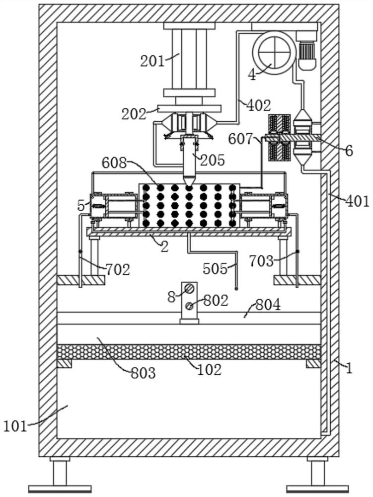
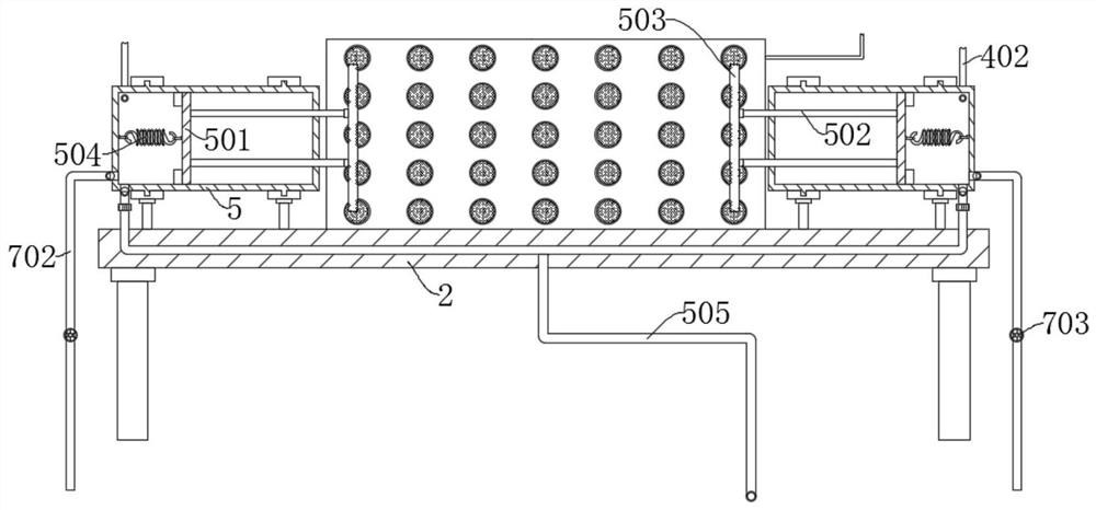
[0040] refer to Figure 1-Figure 9, an automatic drilling machine, comprising a box body 1, the inner wall of the box body 1 is fixedly connected with a workbench 2, and also includes: a water storage cavity 101 arranged in the box body 1, wherein the top inner wall of the box body 1 is provided with a The drilling mechanism for punching the workpiece; the water nozzle 805 is fixedly connected to the punching mechanism; the sleeves 5 are symmetrically arranged with two groups, the two groups of sleeves 5 are fixedly connected to the worktable 2, and the two groups of sleeves 5 A piston disc 1 501 is slidably connected inside; the connecting rod 502 is fixedly connected to the piston disc 1 501, and a clamping plate 503 is fixedly connected to the end of the connecting rod 502 away from the piston disc 1 501. The piston disc 1 501 and the sleeve 5 A tension spring 504 is connected between the inner walls of the bottom; a drain pipe 702 is connected to the sleeve 5, and a soleno...

Embodiment 2

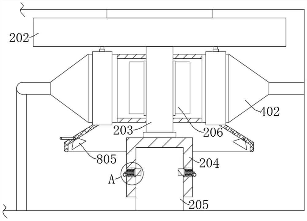
[0051] refer to figure 2 , Figure 7 , an automatic drilling machine, which is basically the same as Embodiment 1. Further, the outer wall of the drill bit 205 is provided with a clamping groove 3, the connecting sleeve 204 is provided with a groove 301, and a connecting block 302 is slidably connected in the groove 301. A spring one 303 is connected between the connection block 302 and the groove 301 , and the connection block 302 is inserted into the card groove 3 .

[0052] A pull rope 304 is fixedly connected to the connection block 302 , and a pull ring 305 is fixedly connected to one end of the pull rope 304 away from the connection block 302 .

[0053] When the drill bit 205 needs to be replaced, the operator pulls the pull ring 305, and the pull ring 305 drives the connecting block 302 to move through the pull rope 304, compressing the spring 1 303, so that the connecting block 302 is moved out from the slot 3 and retracted. In the groove 301, the operator can then ...

Embodiment 3

[0055] refer to figure 1 , Image 6 and Figure 9 , an automatic drilling machine, which is basically the same as Embodiment 1. Further, the inner wall of the box body 1 is provided with a guide assembly, the guide assembly is slidably connected with a scraper 803, and the inner wall of the box body 1 is rotatably connected with a reciprocating screw rod 8 The impeller 3 801 is fixedly installed on one end of the reciprocating screw rod 8 through the pressure relief pipe 505, the scraper 803 is threadedly connected with the reciprocating screw rod 8, the scraper 803 is attached to the surface of the activated carbon filter screen 102, and the box body 1 is provided with a row Feed port 804.

[0056] The guide assembly includes a guide rod 802 , the guide rod 802 is fixedly connected to the inner wall of the box body 1 , and the scraper 803 is slidably connected to the guide rod 802 .

[0057] When the water pressure in the sleeve 5 is greater than the safe value set by the ...


PUM


Abstract

The invention discloses an automatic drilling machine and method, and belongs to the technical field of drilling machines. An automatic drilling machine comprises a box body, a working table is fixedly connected to the inner wall of the box body, the automatic drilling machine further comprises a water storage cavity formed in the box body, and a drilling mechanism used for drilling a workpiece is arranged on the inner wall of the top of the box body; the water spray nozzle is fixedly connected to the punching mechanism; the two sets of sleeves are symmetrically arranged, and the two sets of sleeves are fixedly connected to the workbench; according to the drilling device, a drill bit can be cooled when a workpiece is drilled, so that the service life of the drill bit is prolonged, the workpiece can be automatically clamped and fixed, and after the workpiece is drilled, two sets of clamping plates for clamping and fixing the workpiece are automatically opened, so that the drilling efficiency is improved. And scraps left on the workbench during workpiece punching can be automatically cleaned, so that the working efficiency of the automatic drilling machine is improved, and the surface of the workbench is kept clean and tidy.

Description

technical field [0001] The invention relates to the technical field of drilling machines, in particular to an automatic drilling machine and a method. Background technique [0002] Drilling machine is a general term for machinery and equipment that use a tool that is harder and sharper than the target to leave cylindrical holes or holes on the target by rotary cutting or rotary extrusion. Machines, punching machines, through-hole machines, etc., through drilling precision parts to achieve the desired effect. [0003] At present, when the drilling machine is processing the workpiece to be processed, it is necessary to use a clamping device to fix the workpiece to be drilled on the work surface, and then use the drill bit to drill the hole to be drilled. The hole is automatically clamped, and after the workpiece is drilled, the clamping and limiting mechanism for the workpiece cannot be automatically opened, thereby reducing the efficiency of the drilling machine for drilling...

Claims


Application Information

Patent Timeline
IPC IPC(8): B23B47/00B23Q3/06B23Q11/00B23Q11/10
CPCB23B47/00B23Q3/06B23Q11/10B23Q11/005
Inventor 陈扬宗唐军华
Owner 深圳市易思达软件技术有限公司
Why Eureka
Try Eureka