[0024] The technical solutions in the embodiments of the present invention will be clearly and completely described below with reference to the accompanying drawings in the embodiments of the present invention. Obviously, the described embodiments are only a part of the embodiments of the present invention, but not all of the embodiments. Based on the embodiments of the present invention, all other embodiments obtained by those of ordinary skill in the art without creative efforts shall fall within the protection scope of the present invention.
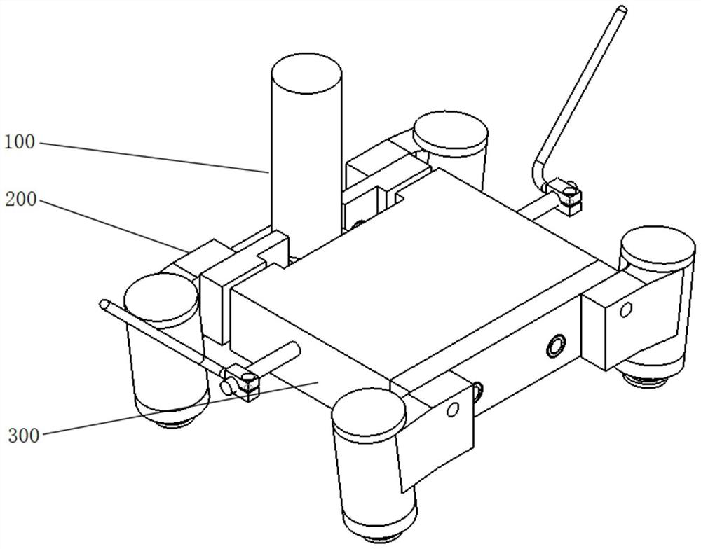
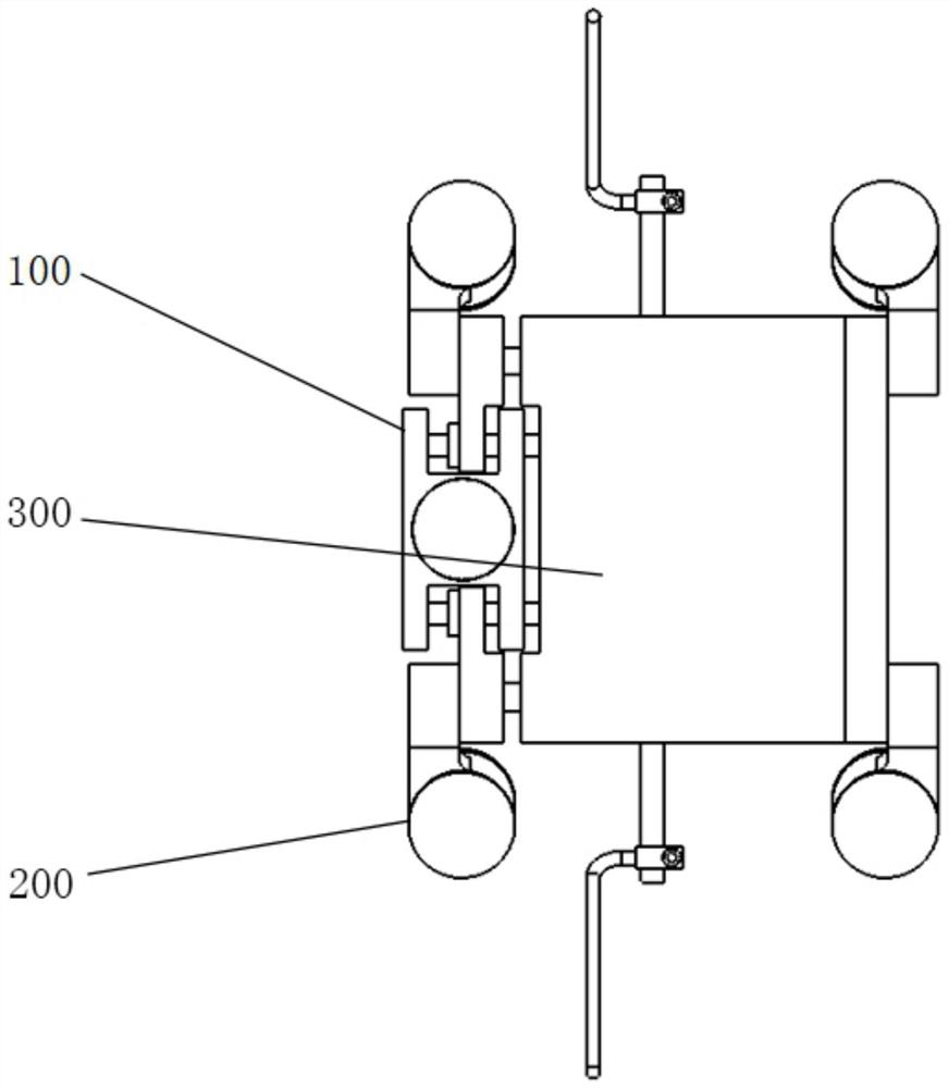
[0025] see Figure 1-7 As shown, the present invention is a segmented clamping type all-position pipeline welding trolley traveling mechanism, including a driving wheel assembly 100, a driven wheel assembly 200 and a single-curve four-wheel host assembly 300, and the driving wheel assembly 100 is assembled on the single-curve four-wheel At one end of the main engine assembly 300, the single-curve four-wheel main engine assembly 300 is assembled on the inner side of the driven wheel assembly 200;
[0026] see Figure 1-5 As shown, the driving wheel assembly 100 includes a motor fixing base 101, a stepping motor 102, a driving wheel 103, and a driving wheel bearing 104. The top of the motor fixing base 101 is bolted to fix the stepping motor 102, and one end of the motor fixing base 101 is fixed by the driving The wheel bearing 104 is equipped with the driving wheel 103, and the output end of the stepping motor 102 penetrates the motor fixing seat 101 and the driving wheel bearing 104 and is fixed to the driving wheel 103;
[0027] see Figure 1-4 , Image 6 As shown, the driven wheel assembly 200 includes four driven wheel sleeves 201, four driven wheels 202, four driven wheel sleeve cover plates 204, a driven wheel connecting block 205 and a left side plate 206, two of which are located on the left side The right side of the driven wheel sleeve 201 is connected with the left side plate 206 by bolts, and the left side of the two driven wheel sleeves 201 located on the right side are connected with the driven wheel connecting block 205 by bolts. The bottom of the driven wheel sleeve 201 A driven wheel 202 is rotatably connected to the inner side of the driven wheel sleeve 201, and a driven wheel sleeve cover plate 204 is assembled on the inner side of the top of the driven wheel sleeve 201;
[0028] see Figure 1-4 , Figure 7 As shown, the single-curve four-wheel main engine assembly 300 includes a housing, two large-diameter through-shafts 301 in the horizontal direction, a large-diameter through-shaft 302 in the vertical direction, two small-diameter through-shafts 303 in the horizontal direction, a large cam baffle 304, and a small cam Baffle plate 305, left locking handle 306, right locking handle 307, four large die springs 308, four small die springs 309, two spring front stops 310, two spring fixed stops 311, four large The cam 312, the small cam 313, the four left bushings 314, the four right bushings 315 and the two bosses 316, the housing, the left side plate 206, the driven wheel connecting block 205 and the inner side of the motor fixing seat 101 are slidably connected with The two large-diameter through-shafts 301 in the horizontal direction are respectively slidably connected to the two ends of the large-diameter through-shafts 301 in the horizontal direction with a left sleeve 314 and a right sleeve 315 , and both the left sleeve 314 and the right sleeve 315 are fixedly connected to the housing , the inner side of the casing is rotatably connected with a large-diameter through-shaft 302 in the vertical direction, four large cams 312 and one small cam 313 are fixed on the outside of the large-diameter through-shaft 302 in the vertical direction, and the angle of the protrusion of the large cam 312 is the same as The included angle between the protruding angles of the small cam 313 is ninety degrees, and by using two horizontal large diameter through shafts 301 to penetrate the single-curve four-wheel host assembly 300, the left side plate 206, the driven wheel connecting block 205 and the motor The fixing base 101, and the single-curve four-wheel main engine assembly 300, the left side plate 206, the driven wheel connecting block 205 and the motor fixing base 101 are fixed by four left bushings 314 and four right bushings 315;
[0029]The two sides of the large-diameter through-shaft 302 in the vertical direction are respectively fixed with a left locking handle 306 and a right locking handle 307 by screws, and two large die springs 308 and two A small die spring 309 is also slidably connected to the inner side of the housing with two horizontal small diameter through shafts 303 , a small cam baffle 305 is fixed on the outside of the two horizontal direction small diameter through shafts 303 , and two horizontal large diameter through shafts 301 A large cam baffle 304 is fixed on the outer side of the shaft, and the large diameter in the horizontal direction penetrates the outer side of the shaft 301 and is located between the large die spring 308 and the small die spring 309. A spring front stop 310 is fixed. The space between the side blocks 310 is used to limit the expansion and contraction of the four large die springs 308. The small diameter in the horizontal direction penetrates the outside of the shaft 303 and is located between the large die spring 308 and the small die spring 309. A spring fixing stop 311 is fixed, and the large cam The left side of the baffle 304 fits the small die spring 309, the right side fits the large cam 312, and the left side of the small cam baffle 305 fits the large and small die spring 309, and the right side fits the small cam 313, thereby making the structure of the mechanism The design is reasonable and compact, which achieves the advantages of light weight, convenient disassembly and assembly, and low processing cost, can meet the requirements of various performance indicators, and effectively prevent the clamping force of the driving wheel from being unable to control the occurrence of damage to the guide rail and wear of the driving wheel 103. Overall improved welding quality and efficiency;
[0030] see Figure 1-4 , Image 6 As shown, in this embodiment, the interior of the four driven wheel sleeves 201 are provided with stepped holes, the interior of the four driven wheel sleeves 201 and at the top and bottom of the stepped holes are equipped with plane bearings 203, the driven wheel The sleeve 201 is rotatably connected to the driven wheel 202 through the plane bearing 203, which can reduce the frictional force generated between the driven wheel 202 and the driven wheel sleeve 201 when the driven wheel 202 rotates, thereby prolonging the service life and greatly improving the use of the driven wheel 202. Effect.
[0031] During use, by rotating the left locking handle 306 and the right locking handle 307 at the same time, the large cam 312 on the vertical large diameter through shaft 302 is driven to rotate, and when the stroke of the large cam 312 reaches half, the large cam baffle is squeezed 304 further drives the driven wheel connecting block 205 and the driven wheel sleeve 201 to move laterally, so that the driven wheel 202 is clamped on the guide rail, and the left locking handle 306 and the right locking handle 307 are further rotated and rotated to drive the small cam 313 to rotate and squeeze Press the small cam baffle 305 to drive the driving wheel assembly 100 to move laterally, so that the driving wheel 103 is clamped on the guide rail. At this time, the stroke of the large cam 312 reaches the maximum, and the tension force of the driven wheel 202 can be obtained. It can complete the up and down walking of the welding trolley on the guide rail.
[0032] In the description of this specification, description with reference to the terms "one embodiment," "example," "specific example," etc. means that a particular feature, structure, material, or characteristic described in connection with the embodiment or example is included in at least one aspect of the present invention. in one embodiment or example. In this specification, schematic representations of the above terms do not necessarily refer to the same embodiment or example. Furthermore, the particular features, structures, materials or characteristics described may be combined in any suitable manner in any one or more embodiments or examples.
[0033] The above-disclosed preferred embodiments of the present invention are provided only to help illustrate the present invention. The preferred embodiments do not exhaust all the details, nor do they limit the invention to only the described embodiments. Obviously, many modifications and variations are possible in light of the contents of this specification. These embodiments are selected and described in this specification in order to better explain the principles and practical applications of the present invention, so that those skilled in the art can well understand and utilize the present invention. The present invention is to be limited only by the claims and their full scope and equivalents.