Shock wave position and waveform sensor based on parallel resistor array
What is Al technical title?
Al technical title is built by PatSnap Al team. It summarizes the technical point description of the patent document.
A resistance array and shock wave technology, applied in the field of shock compression, can solve the problems affecting the accuracy of voltage signal interpretation and identification accuracy of series resistive sensing circuits, shorten the fall time, reduce the equivalent inductance, and reduce the impact Effect
Pending Publication Date: 2022-07-29
SOUTHWEST JIAOTONG UNIV
View PDF8 Cites 0 Cited by
Summary
Abstract
Description
Claims
Application Information
AI Technical Summary
This helps you quickly interpret patents by identifying the three key elements:
Problems solved by technology
Method used
Benefits of technology
Problems solved by technology
In the experiment, it was found that factors such as the parasitic inductance of the electric probe connection wire seriously affect the interpretation accuracy of the voltage signal of the series resistive sensing circuit
The later voltage mutation point in the step-down voltage signal will become smooth, and after being superimposed with the measurement noise, the identification accuracy of the voltage mutation moment will drop significantly
Method used
Image
Click on the blue label to locate the original text in one second.
Reading with bidirectional positioning of images and text.
Examples
Embodiment Construction
[0032] All features disclosed in this specification, or all disclosed steps in a method or process, may be combined in any way except mutually exclusive features and / or steps.
[0033] Combine below Figure 1 to Figure 5 The present invention will be described in detail.
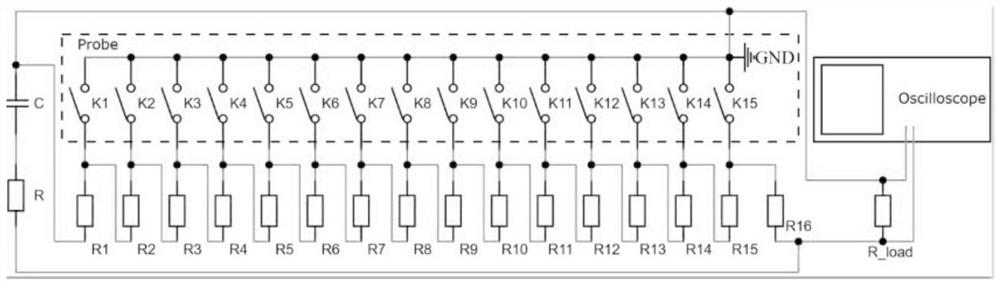
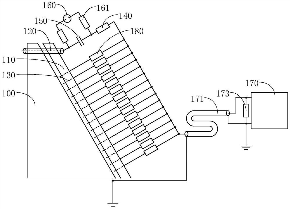
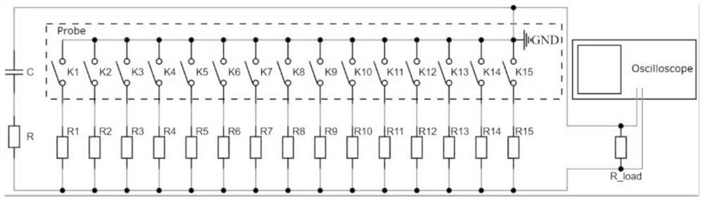
[0034] Please refer to figure 2 and image 3 shown, image 3 The structure in the dotted box is the equivalent structure diagram of the electrical probe array. A shock wave position and waveform sensor based on a parallel resistor array, comprising a sample 100, a probe holder 110, a trigger probe 120, a plurality of electrical probes 130, a first resistor 140, a capacitor 150, a power source 160, a charging resistor 161 and an oscilloscope 170. The probe holder 110 is provided with a trigger probe hole and at least one row of electrical probe holes. One end of the trigger probe 120 passes through the trigger probe hole and the sample 100 . The trigger probe 120 includes a sheath and a wire core. The t...
PUM
Abstract
The invention discloses a shock wave position and waveform sensor based on a parallel resistor array, which comprises a sample, a probe support, a trigger probe, a plurality of electric probes, a first resistor, a capacitor, a power supply, a charging resistor and an oscilloscope, the probe support is provided with trigger probe holes and at least one column of electric probe holes, the electric probes and the electric probe holes are arranged in a one-to-one correspondence manner, and the first resistor is connected with the capacitor. One end of each electric probe penetrates through the corresponding electric probe hole, the other end of each electric probe is connected with a second resistor, the multiple second resistors are connected in parallel, and the ends, away from the electric probes, of the multiple second resistors are connected with an oscilloscope through coaxial cables. When the shock wave position and waveform sensor is in a steady state, current flows through a plurality of connecting wires, and a plurality of second resistors are sequentially connected into a circuit, so that the magnitude of the current flowing through the plurality of wires is changed at the same time, equivalently, parasitic inductors of different connecting wires are connected in parallel, the equivalent inductance value is reduced, and the influence of measurement noise on voltage sudden change point interpretation is reduced. And the time precision of voltage abrupt change point interpretation is improved.
Description
technical field [0001] The invention relates to the field of shock compression, in particular to a shock wave position and waveform sensor based on a parallel resistance array. Background technique [0002] The propagation law and stability of shock waves have always been the focus of astrophysics, inertial confinement fusion and explosion mechanics. In practical engineering applications, the shock wave will deform when it reaches any interface. The specific deformation characteristics are closely related to the physical properties of the material. Scholars have carried out some useful explorations through theory and experiments. In terms of theory, D'yakov first studied the stability of shock waves by using non-uniform disturbances, and gave a stability criterion. He found that in the case of instability, the shock wave disturbances increased exponentially with time. Lordanskii has a different view. He believes that the shock wave perturbation follows the law of exponentia...
Claims
Application Information
Patent Timeline
Application Date:The date an application was filed.
Publication Date:The date a patent or application was officially published.
First Publication Date:The earliest publication date of a patent with the same application number.
Issue Date:Publication date of the patent grant document.
PCT Entry Date:The Entry date of PCT National Phase.
Estimated Expiry Date:The statutory expiry date of a patent right according to the Patent Law, and it is the longest term of protection that the patent right can achieve without the termination of the patent right due to other reasons(Term extension factor has been taken into account ).
Invalid Date:Actual expiry date is based on effective date or publication date of legal transaction data of invalid patent.