Hot surface cavitation efficiency-increasing and resistance-reducing test device and method

The technology of a test device and test method is applied in the field of hot surface cavitation synergistic drag reduction test device, which can solve the problems of poor continuous drag reduction effect, inability to realize stable attachment of microbubbles, and high energy consumption, and achieve low cost, Simple operation and good repeatability

Active Publication Date: 2022-07-29
XIAMEN UNIV
View PDF27 Cites 0 Cited by
  • Summary
  • Abstract
  • Description
  • Claims
  • Application Information

AI Technical Summary

Problems solved by technology

However, the microbubbles generated by the conventional ventilation method cannot stay stably, and continuous ventilation is required, which consumes a lot of energy and the microbubbles are more likely to enter the high flow rate area, so the stable attachment of the microbubbles to the wall cannot be achieved, and the continuous drag reduction effect is not good.

Method used


Image

  • Hot surface cavitation efficiency-increasing and resistance-reducing test device and method
  • Hot surface cavitation efficiency-increasing and resistance-reducing test device and method
  • Hot surface cavitation efficiency-increasing and resistance-reducing test device and method

Examples


Embodiment 1

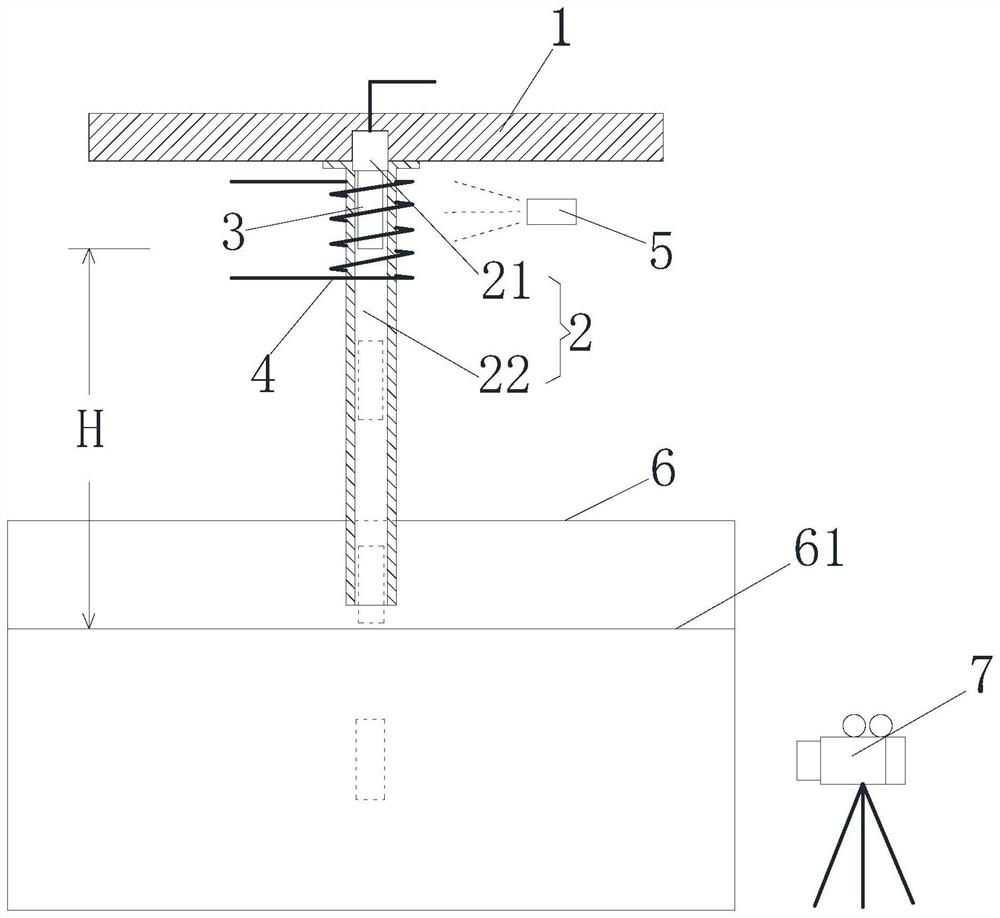
[0043] like figure 1 As shown, a thermal surface cavitation efficiency and drag reduction test device includes a test bench 1 , a transmitter 2 , a metal body 3 , a heater 4 , a thermometer 5 , a water tank 6 and a photographing device 7 . Wherein, the test table 1 may be a fixed table set fixedly, and may also be a movable table whose height can be adjusted up and down. The test bench 1 includes, but is not limited to, a transmitter 2 installed with a metal body 3 detachably and vertically connected. In addition, the number of transmitters 2 can be increased as required and arranged at intervals.

[0044] like figure 1As shown, in one specific embodiment, the transmitter 2 includes an electromagnet 21 and a conduit 22 . The upper end of the guide tube 22 is connected to the test stand 1 , and is provided with an electromagnet 21 for attracting the transmitter 2 . Specifically, the upper end of the conduit 22 and the upper end of the electromagnet 21 are both vertically and...

Embodiment 2

[0073] like Figure 1 to Figure 8 As shown, in this specific embodiment, a thermal surface cavitation synergistic drag reduction test device, compared with the thermal surface cavitation synergy drag reduction test device described in the first embodiment, also includes a pick-and-place device. , the pick-and-place device mainly includes a two-dimensional sliding table structure 81 , a collection tray 82 and a lifting device 83 .

[0074] like Figure 8 As shown, specifically, the test bench 1 is provided with an ejection opening 11 and an ejection opening 12 , and a conduit 22 is arranged at the lower port of the ejection opening 12 . The electromagnet 21 is disposed on the test stand 1 through the two-dimensional sliding table structure 81 so as to be able to move back and forth between the cartridge taking port 11 and the cartridge discharging port 12 . The two-dimensional sliding table structure 81 includes, but is not limited to, it is mainly composed of a first electri...

Embodiment 3

[0078] like Figure 1 to Figure 10 As shown, in this specific embodiment, a thermal surface cavitation synergy and drag reduction test device, compared with the thermal surface cavitation synergy and drag reduction test device described in the second embodiment, the test bench passes the swing mechanism. It is arranged above the water tank in a swingable and adjustable manner, and is used to change the water entry angle of the metal body, so as to facilitate the study of the oblique injection of the metal body into the water.

[0079] like Figure 1 to Figure 10 As shown, specifically, the swing mechanism includes but is not limited to a connecting arm 91, a swing arm 92, a linkage shaft 93 and a drive motor 94, the left and right ends of the test bench 1 are provided with swing arms 92, and the other end of the swing arm 92 is pivotally connected There are connecting arms 91 connected to the fixed surface. The two swing arms 92 are connected to each other through a linkage ...


PUM

PropertyMeasurementUnit
Lengthaaaaaaaaaa
Diameteraaaaaaaaaa

Abstract

The invention discloses a hot surface cavitation efficiency-increasing and resistance-reducing test device and method, and relates to the field of fluid mechanics, and the method comprises the following steps: a heater heats a metal body connected with an emitter; the emitter releases the metal body; adjusting the angle of the test bed to enable the metal body to enter water at different angles; the photographing device photographs a whole-process image after the metal body enters water; the metal bullet is taken back by the pick-and-place device; and calculating the drag reduction efficiency according to the obtained whole process image. Therefore, the invention provides a new thought and technical basis for high-speed underwater design: by heating the metal body, the metal body generates a bubble air film attached to the near wall surface of the metal body in underwater movement, so that the resistance is effectively reduced, no adverse effect is generated on the environment, and specific test equipment and method are provided; the device is used for quantitatively testing the drag reduction rate of a heated metal body entering water at different temperatures and angles, and has the advantages of simplicity in operation, good quantizability and repeatability and the like.

Description

technical field [0001] The invention relates to the field of fluid mechanics, in particular to a thermal surface cavitation efficiency enhancement and drag reduction test device and method. Background technique [0002] The resistance of an object moving in a fluid is proportional to the density of the fluid, so the resistance of a vehicle during its motion in water is about 1000 times that of an aircraft in the air. Taking ships as an example, the resistance of ships in water mainly includes pressure difference resistance, wave-making resistance and frictional resistance, among which frictional resistance accounts for about 50% to 80% of the total resistance. It has important practical significance in terms of speed and increase of voyage. [0003] Traditional micro-bubble drag reduction, also known as air curtain and cavitation drag reduction, is to create air bubbles on the surface of objects to achieve the effect of drag reduction and noise reduction. The finely disper...

Claims


Application Information

Patent Timeline
IPC IPC(8): G01M10/00G01K13/00
CPCG01M10/00G01K13/00Y02T70/10
Inventor 朱睿张焕彬庄启彬温潍齐何星宇刘志荣
Owner XIAMEN UNIV
Why Eureka
Try Eureka