Abrasion resistance detection device for automobile steering device
A technology of automobile steering gear and detection device, which is applied in the direction of measuring device, vehicle steering/bump performance, test wear resistance, etc., can solve the problems of low detection efficiency, inconvenient comparison experiment, and inability to batch detection, etc., to improve detection Efficiency, the effect of adjusting the resistance of the rack
- Summary
- Abstract
- Description
- Claims
- Application Information
AI Technical Summary
Problems solved by technology
Method used
Image
Examples
Embodiment 1
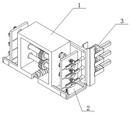
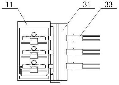
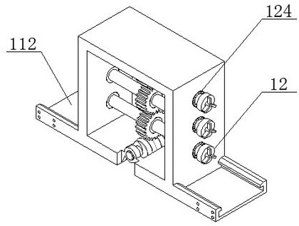
[0050] refer to figure 1 and figure 2 As shown, an automobile steering gear wear resistance detection device includes a main detection box 1, a batch rack 2 and a pressing mechanism 3. The main detection box 1 includes a box rack 11 and a transmission mechanism 12. The transmission mechanism 12 is evenly arranged in the box The middle part of the frame 11, and the transmission mechanism 12 is rotatably connected with the box frame 11. The present invention designs an automobile steering gear wear resistance detection device by studying the structure and use process of the traditional steering gear wear resistance detection equipment, which is convenient When the user needs to use it, the guide frame 112 can be installed through the middle case 111. In this way, the user can install the gear rod and the rack to be tested on the test vertical plate 22, that is, the gear rod to be tested. Insert into the rotating sleeve 223 on the test vertical plate 22, and then install the ra...
Embodiment 2
[0055] refer to Figure 14 and Figure 15 As shown, the movable frame 23 includes a front plate 2301 and an H-shaped slider 2302. The front plate 2301 is arranged on the front end surface of the H-shaped slider 2302, and the front plate 2301 is fixedly connected with the H-shaped slider 2302. The left and right sides of the front plate 2301 A side plate 2303 is arranged symmetrically on the side. The side plate 2303 and the front plate 2301 are integrally formed. When the movable frame 23 needs to be used, an H-shaped slider 2302 can be installed on the front plate 2301, so that the front plate 2301 can pass the H-shaped slider 2302. It is stably installed inside the horizontal groove 222 to ensure that the front plate 2301 can slide flexibly inside the horizontal groove 222 through the H-shaped slider 2302. The plate 2303 is used to clamp both ends of the rack, and at the same time, bolts are installed on the side plate 2303 to assist in clamping and fixing the rack.
[005...
PUM
 Abstract
Description
Claims
Application Information
 - R&D
- Intellectual Property
- Life Sciences
- Materials
- Tech Scout
- Unparalleled Data Quality
- Higher Quality Content
- 60% Fewer Hallucinations
Browse by: Latest US Patents, China's latest patents, Technical Efficacy Thesaurus, Application Domain, Technology Topic, Popular Technical Reports.
© 2025 PatSnap. All rights reserved.Legal|Privacy policy|Modern Slavery Act Transparency Statement|Sitemap|About US| Contact US: help@patsnap.com


