Long-distance laser light path calibration system and method based on machine vision

A machine vision and optical path calibration technology, applied in the field of laser calibration, can solve the problems of difficult automatic adjustment of the laser and laser irradiation at the target position, etc., to achieve the effect of low cost and improve the degree of automation

Pending Publication Date: 2022-07-29
SHANGHAI INST OF TECH
View PDF0 Cites 0 Cited by
  • Summary
  • Abstract
  • Description
  • Claims
  • Application Information

AI Technical Summary

Problems solved by technology

However, in many cases, when the position of the laser is far away from the target point, it is difficult to irradiate the laser at the target position. Therefore, it is difficult to realize the automatic adjustment of the position of the laser at a relatively long distance in the prior art.

Method used


Image

  • Long-distance laser light path calibration system and method based on machine vision
  • Long-distance laser light path calibration system and method based on machine vision
  • Long-distance laser light path calibration system and method based on machine vision

Examples


Embodiment 1

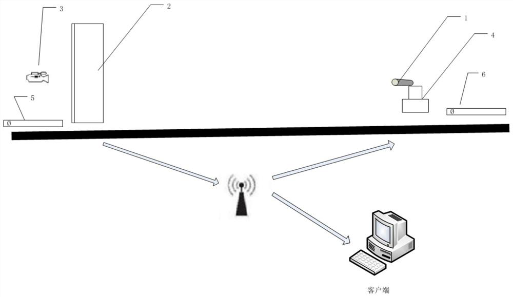
[0034] The invention provides a long-distance laser optical path calibration system based on machine vision, comprising: a laser 1, used for emitting a laser beam; a target surface 2, used for receiving the laser beam of the laser; a camera 3, used for taking pictures of light spots; The machine 4 is used to control the position of the laser; the first adjustment control module 5 is used to obtain the position of the light spot and the error between the light spot and the center of the target surface 2; the second adjustment control module 6 is used to control the steering gear 4 through the error. Adjust the position of the laser 1; the laser spot is generated by the laser 1, and the laser spot is presented on the target surface 2. The side of the target surface 2 away from the laser 1 is provided with a camera 3. The camera 3 collects the spot image on the target surface 2, and the laser 1 is fixed On the steering gear 4 , the first adjustment control module 5 , the second ad...

Embodiment 2

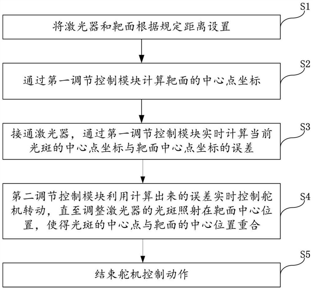
[0042] like figure 2 As shown, based on the system provided in the first embodiment, the present invention also provides a long-distance laser optical path calibration method based on machine vision, including the following steps:

[0043] Step S1, set the laser and the target surface according to the specified distance;

[0044] Step S2, calculating the coordinates of the center point of the target surface through the first adjustment control module;

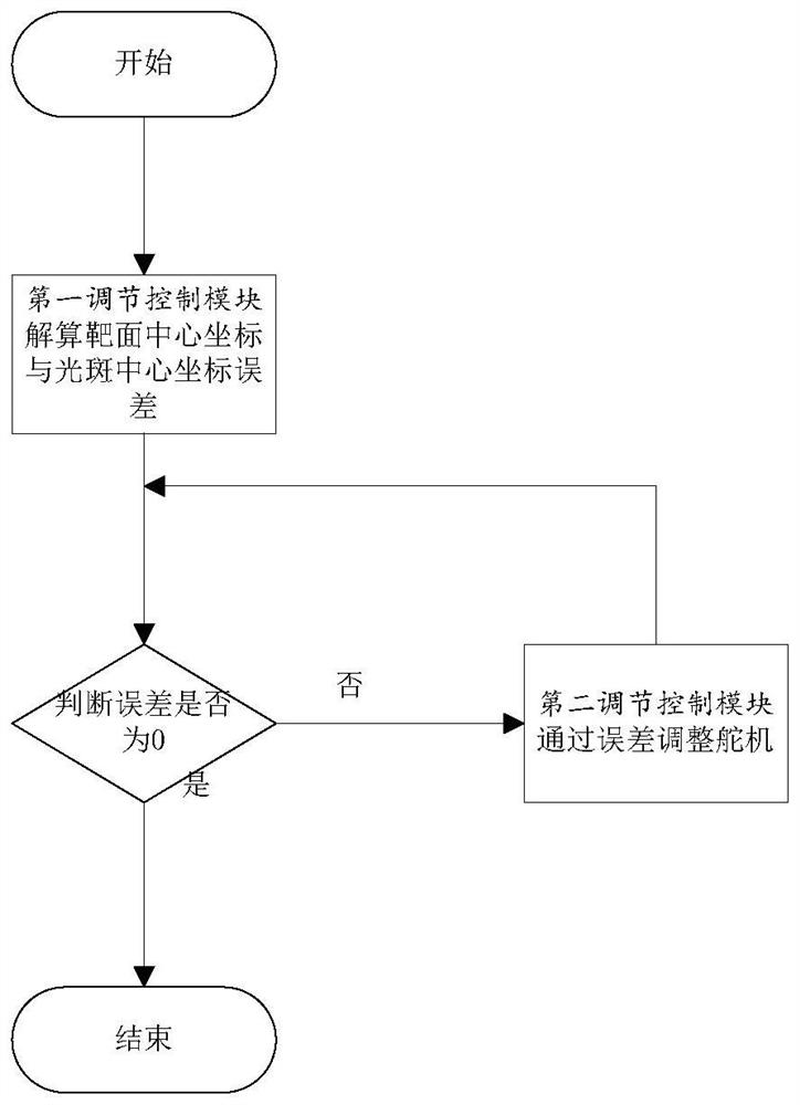
[0045] Step S3, turn on the laser, and calculate the error between the coordinates of the center point of the current spot and the coordinates of the center point of the target surface in real time through the first adjustment control module;

[0046]Step S4, the second adjustment control module uses the calculated error to control the rotation of the steering gear in real time, until the spot of the adjustment laser is irradiated on the center position of the target surface, so that the center point of the spot coincides wit...


PUM


Abstract

The invention discloses a remote laser light path calibration system and method based on machine vision, and the system comprises a laser, a target surface, a camera, a steering engine, and a first adjustment control module which is used for obtaining the position of a light spot and the error between the light spot and the center of the target surface; the second adjusting control module is used for adjusting the position of the laser through an error control steering engine; a laser spot is generated through a laser and is presented on a target surface, a camera is arranged on the side, away from the laser, of the target surface, the camera collects a spot image on the target surface, and the laser is fixed to a steering engine. Thus, the machine vision technology is adopted, error data are calculated through an algorithm, then the steering engine is controlled through the single chip microcomputer, the position of the laser device can be automatically adjusted, the laser device irradiates the target position, and the laser device has the advantages of being wider in application range, lower in cost, higher in automation degree and higher in precision.

Description

technical field [0001] The invention relates to the technical field of laser calibration, in particular to a long-distance laser optical path calibration system and method based on machine vision. Background technique [0002] Machine vision is a rapidly developing branch of artificial intelligence. Simply put, machine vision is to use machines instead of human eyes to make measurements and judgments. The machine vision system converts the captured target into an image signal through machine vision products, namely image capture device, CMOS camera and CCD camera, and transmits it to a dedicated image processing system to obtain the morphological information of the captured target, according to the pixel distribution and brightness. , color and other information are converted into digital signals; the image system performs various operations on these signals to extract the characteristics of the target, and then controls the on-site equipment actions according to the result...

Claims


Application Information

Patent Timeline
Patent Type & Authority Applications(China)
IPC IPC(8): H01S3/101H01S3/00H01S5/00H01S5/06G01B11/00
CPCH01S3/0014H01S3/101H01S5/0014H01S5/06G01B11/00
Inventor 杨明来席泽鹏曹振丰张方文海伦陈威晁阳张雪灵王轩方婷婷
Owner SHANGHAI INST OF TECH
Why Eureka
Try Eureka