
Printed circuit board corrosion drilling equipment and drilling process

A technology for printed circuit boards and drilling equipment, which is applied in the direction of printed circuits, printed circuit manufacturing, manufacturing tools, etc. It can solve the problems of high transfer temperature and unclear transfer, so as to improve the yield and avoid circuit transfer Unclear, cost-reducing effects

Pending Publication Date: 2022-07-29
严天才
View PDF8 Cites 0 Cited by
  • Summary
  • Abstract
  • Description
  • Claims
  • Application Information

AI Technical Summary

Problems solved by technology

[0006] Aiming at the deficiencies of the prior art, the present invention provides a printed circuit board corrosion drilling equipment, which has the advantages of clear transfer circuit and anti-scalding, and solves the problems of unclear transfer and high transfer temperature

Method used


Image

  • Printed circuit board corrosion drilling equipment and drilling process
  • Printed circuit board corrosion drilling equipment and drilling process
  • Printed circuit board corrosion drilling equipment and drilling process

Examples


Embodiment Construction

[0038] The technical solutions in the embodiments of the present invention will be clearly and completely described below with reference to the accompanying drawings in the embodiments of the present invention. Obviously, the described embodiments are only a part of the embodiments of the present invention, rather than all the embodiments. Based on the embodiments of the present invention, all other embodiments obtained by those of ordinary skill in the art without creative efforts shall fall within the protection scope of the present invention.

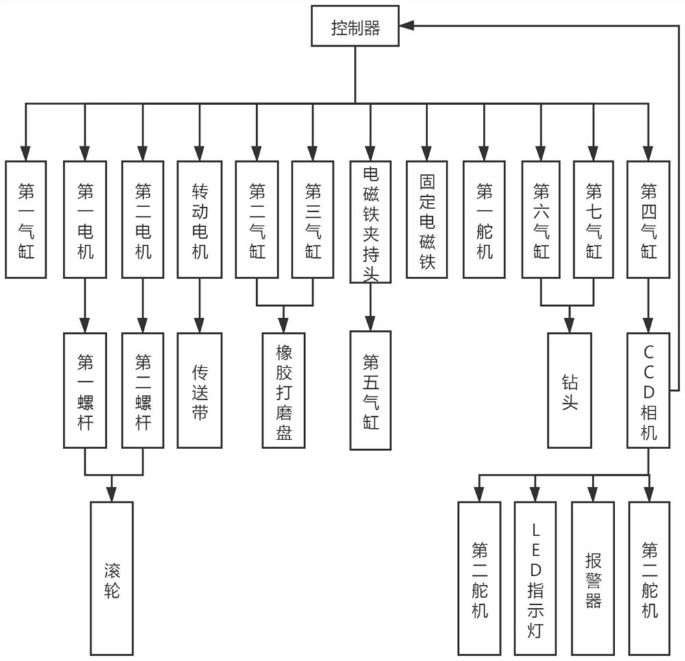
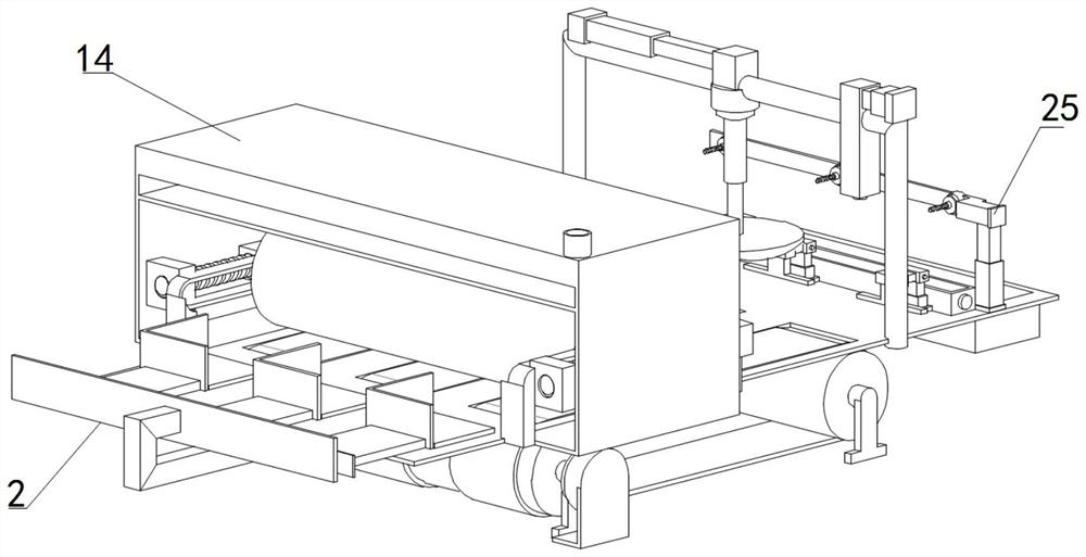
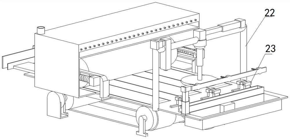
[0039] see Figure 1-10 , a printed circuit board corrosion drilling equipment, including a processing table 1, one end of the processing table 1 is provided with a pushing mechanism 2, and one end of the processing table 1 close to the pushing mechanism 2 is fixedly provided with an auxiliary frame 3, because most of the The circuit board is square, so the auxiliary frame 3 is designed to be rectangular, which is suitable for the pr...


PUM


Abstract

The invention relates to the technical field of circuit board manufacturing, and discloses printed circuit board corrosion drilling equipment and a drilling process, the printed circuit board corrosion drilling equipment comprises a processing table, a pushing mechanism is arranged at one end of the processing table, an auxiliary frame is fixedly arranged at the end, close to the pushing mechanism, of the processing table, and sliding rails are fixedly arranged on the two sides of the end, close to the auxiliary frame, of the processing table; the two sliding rails are provided with rolling wheels, the two ends of each rolling wheel are provided with a first sliding block and a second sliding block respectively, heat insulation layers are arranged at the positions, corresponding to the sliding rails, of the machining table, three conveying grooves are formed in the positions, corresponding to the three auxiliary frames, of the surface, corresponding to the sliding rails, of the machining table, and conveying belts are arranged in the three conveying grooves. A first roller and a second roller are sleeved with the two ends of each conveying belt respectively, fixing supports are arranged at the two ends of each first roller and the two ends of each second roller, a rotating motor is arranged on one side of each first roller, and a motor fixing frame is fixedly arranged outside each rotating motor. According to the equipment, circuit corrosion errors caused by unclear circuit transfer can be avoided, so that the number of failed products is reduced.

Description

technical field [0001] The invention relates to the technical field of circuit board manufacturing, in particular to a printed circuit board corrosion drilling equipment and a drilling process. Background technique [0002] Printed circuit boards, also known as printed circuit boards, are the provider of electrical connections for electronic components. Printed circuit boards are often represented by "PCB". Its development has a history of more than 100 years; its design is mainly layout design; The main advantage of using circuit boards is to greatly reduce wiring and assembly errors, improve the automation level and production labor rate, and can be divided into single-sided, double-sided, four-layer, six-layer and other multi-layer circuits according to the number of circuit boards. plate. It is constantly changing with the advancement of process technology, but in principle, what remains unchanged is that a complete PCB circuit board needs to go through printing circuit...

Claims


Application Information

Patent Timeline
Patent Type & Authority Applications(China)
IPC IPC(8): H05K3/20H05K3/00B24B27/033B24B49/12G01N21/956
CPCH05K3/207H05K3/0047H05K3/0055H05K3/20B24B27/033B24B49/12G01N21/956G01N2021/95638Y02W30/82
Inventor 严天才杜琳
Owner 严天才
Learn More