High-rise building hydraulic discharging platform device and working method thereof

A technology for unloading platforms and high-rise buildings, applied in the processing of building materials, construction, building structure, etc., can solve problems such as hidden safety hazards, troublesome lifting and difficult to push the loading rack, and achieve the effect of reducing unloading resistance.

Pending Publication Date: 2022-08-02
别金全
View PDF0 Cites 1 Cited by
  • Summary
  • Abstract
  • Description
  • Claims
  • Application Information

AI Technical Summary

Problems solved by technology

[0004] 1. When the existing unloading platform is in use, the material is unloaded onto the movable loading rack on the platform, and manual or mechanical equipment is required to push the loading rack into the interior of the floor, and then the workers will unload the material. During manual unloading, personnel need to walk to the unloading platform, which poses certain safety hazards. At the same time, when loading materials, it is easy to cause the loading frame to slide, and if the material is loaded too much, the overall mass will be larger and the loading time will be higher. The rack is difficult to push and it is not convenient for material transfer;
[0005] 2. The existing unloading platforms are generally fixed on the corresponding floors. After the construction of this floor is completed, when it is necessary to construct other floors, it needs to be hoisted to the designated platform by special lifting equipment, and then carried out Positioning installation, lifting is troublesome, and the whole positioning and installation process is also very inconvenient;

Method used


Image

  • High-rise building hydraulic discharging platform device and working method thereof
  • High-rise building hydraulic discharging platform device and working method thereof
  • High-rise building hydraulic discharging platform device and working method thereof

Examples


Embodiment 1

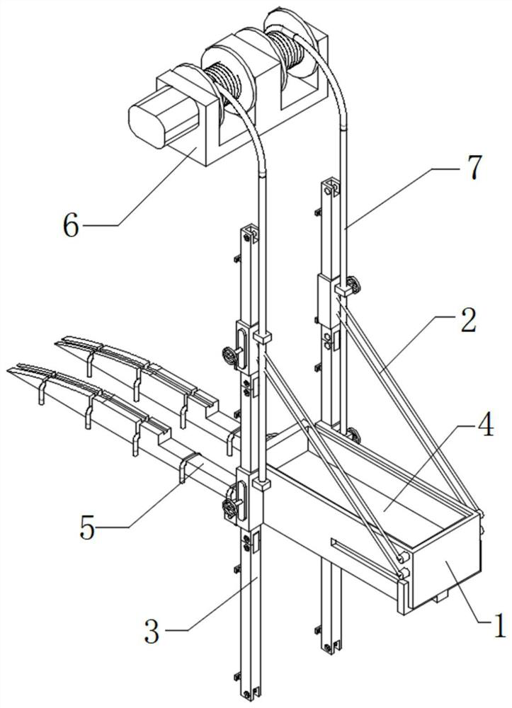
[0052] like Figure 1-8 Shown is a high-rise building hydraulic unloading platform device and its working method, comprising a unloading platform main body 1 and a slidable storage hopper 4 arranged inside the unloading platform main body 1;

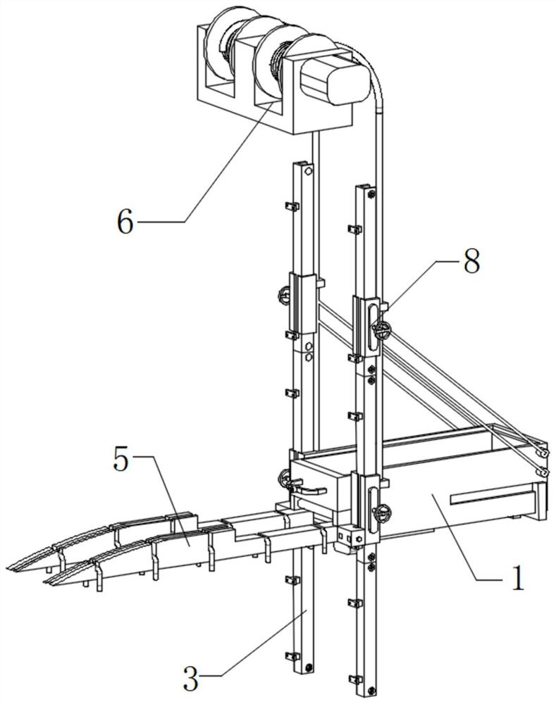
[0053] The unloading platform main body 1, one end of the unloading platform main body 1 is fixedly installed with the unloading slide rail 5, the two sides of the unloading platform main body 1 are provided with spliced ​​slide rails 3 for height lifting, and the other end of the unloading platform main body 1 is provided A cable-stayed cable 2 is fixedly installed, and a sliding sleeve 8 is fixedly connected to the outer surface of the unloading platform main body 1 and the end of the cable-stayed 2 , and the sliding sleeve 8 is fixedly installed on the outer surface of the spliced ​​slide rail 3 . , the top of the spliced ​​slide rail 3 is provided with a wire reel 6, and the inside of the wire reel 6 is wound with a lifting wire 7, a...

Embodiment 2

[0058] like Figure 1-8 Shown is a high-rise building hydraulic unloading platform device and its working method, comprising a unloading platform main body 1 and a slidable storage hopper 4 arranged inside the unloading platform main body 1;

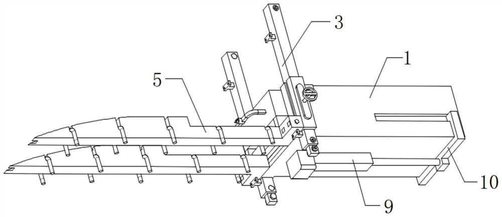
[0059] Storage hopper 4, the bottom of the storage hopper 4 is provided with a sliding support frame 11, the lower surface of the unloading platform main body 1 is provided with a hydraulic telescopic rod 9, the output end of the hydraulic telescopic rod 9 is fixedly connected with the sliding support frame 11, and the sliding support frame 11 A rotating flap 14 is rotatably connected to the inner top of the rotating flap 14, and a rotating strut 18 is hinged on the lower surface of the end of the rotating flap 14. The other end of the rotating strut 18 is internally rotatably connected with a sliding shaft 16, and the two ends of the sliding shaft 16 slide respectively. Connected to both sides of the inner wall of the main body 1 of the...

Embodiment 3

[0063] like Figure 1-8 Shown is a high-rise building hydraulic unloading platform device and its working method, comprising a unloading platform main body 1 and a slidable storage hopper 4 arranged inside the unloading platform main body 1;

[0064] The pulley is rollingly connected to the upper surface of the rotating flap 14, the slideway 25 is the same height as the sliding support frame 11, the outer surface of the storage hopper 4 is fixedly connected with a discharge handle 26, and the middle of the discharge handle 26 is fixedly welded with a fixed sleeve 27 , a pull rod 28 is movably inserted inside the fixed sleeve 27, and a T-shaped clamping rod 29 is movably inserted on both sides of the lower surface of the storage hopper 4. The sliding support frame 11 is movably clamped, the storage hopper 4 is provided with a spring 31 in the internal measurement, the spring 31 is in contact with the top of the T-shaped clamping rod 29, the top of the T-shaped clamping rod 29 i...


PUM


Abstract

The invention discloses a high-rise building hydraulic discharging platform device and a working method thereof, and relates to the field of building construction discharging. According to the high-rise building hydraulic discharging platform device and the working method thereof, a storage hopper is arranged in a discharging platform main body, a sliding supporting frame is arranged at the bottom of the storage hopper, a hydraulic telescopic rod for driving the sliding supporting frame is arranged on the lower surface of the discharging platform main body, and a rotating turning plate is rotationally connected to the inner top of the sliding supporting frame; a rotary supporting rod is movably hinged to the lower surface of the end of the rotary turning plate and slidably connected to the inner wall of the discharging platform body through a sliding shaft. According to the high-rise building hydraulic discharging platform device and the working method thereof, by starting the hydraulic telescopic rod, the connecting frame slides towards the interior of a floor, meanwhile, the tail end of the rotating turning plate is tilted upwards, the storage hopper slides into the sliding way from the rotating turning plate, and therefore discharging resistance is reduced, and meanwhile the high-rise building hydraulic discharging platform device is safer.

Description

technical field [0001] The invention relates to the technical field of unloading in building construction, in particular to a high-rise building hydraulic unloading platform device and a working method thereof. Background technique [0002] The unloading platform is a variety of temporary operating platforms and operating racks that are often erected on the construction site. They are generally installed on the outer wall of the building. The main function is to facilitate the lifting of materials to the The designated floor, and then push the material to the interior of the floor through the unloading platform. [0003] However, there are the following problems in the actual use process; [0004] 1. When the existing unloading platform is in use, the materials are unloaded to the movable loading racks on the platform, and manual or mechanical equipment is required to push the loading racks into the floor, and then the workers will unload the materials and put them on the f...

Claims


Application Information

Patent Timeline
Patent Type & Authority Applications(China)
IPC IPC(8): E04G21/16
CPCE04G21/166
Inventor 别金全
Owner 别金全
Why Eureka
Try Eureka