
External combustion engine

An external combustion engine, jet engine technology, applied in combustion engines, gas turbines, internal combustion piston engines, etc., can solve the problems of increased friction coefficient, low air utilization, low efficiency, etc., to improve the gas compression ratio and improve the output shaft. Torque, simple structure effect

Pending Publication Date: 2022-08-02
李秋辐
View PDF0 Cites 0 Cited by
  • Summary
  • Abstract
  • Description
  • Claims
  • Application Information

AI Technical Summary

Problems solved by technology

Among the above engines, the lowest efficiency is the internal combustion engine. Due to the use of the four-stroke cycle and the crank-link mechanism, it brings many disadvantages to the internal combustion engine. First, the structure is complex and the friction coefficient is increased. Secondly, only one of the four strokes is the intake air. , but the amount of solvent in the cylinder is limited, the air utilization rate is low, and the fuel supply cannot be fully burned when the fuel supply is long. In addition, the initial connecting rod crank operation of the explosive stroke is near the dead point, which offsets part of the energy. Multiple stroke cycles, crank The form of the connecting rod and the cumbersome process limit its speed. Three strokes consume energy, and the energy of one stroke can not be fully utilized and exerted. The power is transmitted from the inside to the flywheel shaft through a series of problems, and the energy is broken Many buckles, so it caused inefficiency, but because it is widely used in fixed occasions, the improvement of this technology is of great significance

Method used


Image

  • External combustion engine
  • External combustion engine
  • External combustion engine

Examples


Embodiment Construction

[0023] The technical solutions in the embodiments of the present invention will be clearly and completely described below with reference to the accompanying drawings in the embodiments of the present invention. Obviously, the described embodiments are only a part of the embodiments of the present invention, rather than all the embodiments. Based on the embodiments of the present invention, all other embodiments obtained by those of ordinary skill in the art without creative efforts shall fall within the protection scope of the present invention.

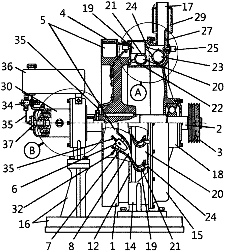
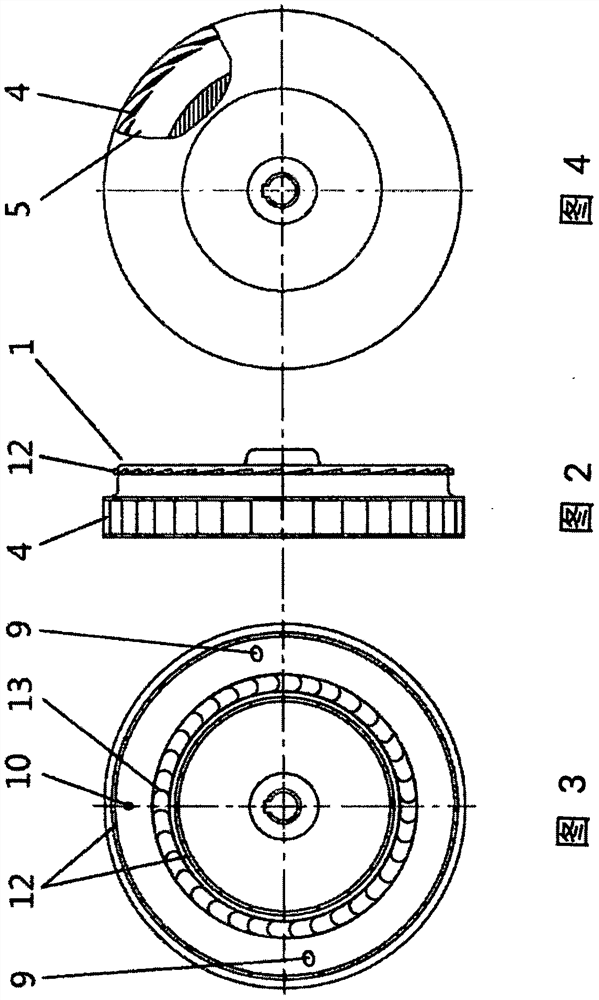
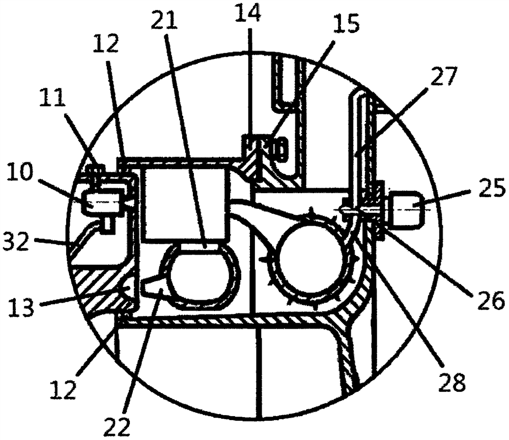
[0024] like figure 1As shown in 16, an external combustion engine includes four parts: rotor, stator, cooling system, and oil-electric system. The rotor includes a flywheel 1, a flywheel shaft 2, an output wheel 3, a guide vane 4, an air chamber 5, a jet engine 6, an outer air passage 7, a tail nozzle 8, a tail nozzle 9, a rocket starter 10, and fuel filling. Bolts 11 , micro-shaped anti-leakage vanes 12 , steam reversal vortex 13 ....


PUM


Abstract

According to the external combustion engine, a flywheel and a flywheel shaft are in stationary fit, the flywheel shaft and a tilting fillet are rotationally connected and fixed to a machine base to form a swing mechanism, the characteristic that the flywheel is high in linear speed is utilized, a jet engine with excellent performance is arranged on the outer circle of the flywheel, tail jet recoil force enables the flywheel to rotate around the circle, and the flywheel shaft is driven to achieve power output. The jet engine can be applied to fixed occasions; the kinetic energy of the flywheel is further enhanced by the counter-acting force generated by a reverse flow vortex sheet arranged in a reverse flow cover fixed on the base; cooling water becomes steam in the waste gas channel, the temperature and pressure are increased step by step and act on the flywheel through the nozzle, and the flywheel obtains a third acting force; compared with an internal combustion engine which can only output residual power to a flywheel shaft through various kinds of friction, consumption and counteracting, an external combustion engine utilizes the direct action of a high-efficiency jet engine, the rotating speed is improved through multi-direction force supply and single-cycle rotation, the outer end action is achieved, and the power inward transmission efficiency is greatly improved. The technology has the advantages of simple structure, easiness in manufacturing, low manufacturing cost and the like.

Description

Technical field: [0001] The technology belongs to the field of engines, and specifically relates to an external combustion engine. Background technique: [0002] The engine is an indispensable power tool in many occasions. For example, the jet engine adopts the principle of air ramming, which directly bursts to do power without intermediate transmission links. It has a simple structure, light weight and high efficiency, and is suitable for high-speed aircraft. Jet turbines solve the flight speed requirements and start-up problems. Although the structure is complex and the efficiency is relatively low, it has strong adaptability and is widely used in the aviation industry. Internal combustion engines including diesel engines and gasoline engines are suitable for fixed occasions such as motor vehicles, ships, and generator sets. Among the above engines, the lowest efficiency is the internal combustion engine. Due to the use of a four-stroke cycle and a crank connecting rod me...

Claims


Application Information

Patent Timeline
IPC IPC(8): F02K3/02F02K7/14F02C3/00F02C7/27F02C7/16F01D9/04F02K1/58F04D25/04F01D1/36
CPCF02K3/025F02K7/14F02C3/00F02C7/27F02C7/16F01D9/041F02K1/58F04D25/045F01D1/36Y02T10/12
Inventor 李秋辐
Owner 李秋辐
Learn More