Novel devolatilization device

A devolatilizer, a new type of technology, applied in the direction of evaporator accessories, chemical instruments and methods, separation methods, etc., can solve the problems of insufficient separation of polymers, short effective devolatilization distance, and influence on devolatilization effect, so as to avoid material The effect of flow dead zone, avoiding temperature discontinuity, and improving product quality

Pending Publication Date: 2022-08-05
广东寰球广业工程有限公司
View PDF0 Cites 0 Cited by
  • Summary
  • Abstract
  • Description
  • Claims
  • Application Information

AI Technical Summary

Problems solved by technology

When the distribution pipe is installed on the tank wall, the distribution pipe occupies the straight section of the tank wall, and the effective devolatilization distance in the vertical direction is short, which affects the devolatilization effect
In addition, during devolatilization, the devolatilization and gasification of the medium in the equipment produces a phase change. The phase change from liquid to gas needs to absorb heat. For example, the devolatilizer cannot be completely covered with heat transfer oil. It is easy to cause the polymer to be insufficiently separated at low temperature, which will affect the product quality

Method used


Image

  • Novel devolatilization device
  • Novel devolatilization device
  • Novel devolatilization device

Examples


Embodiment Construction

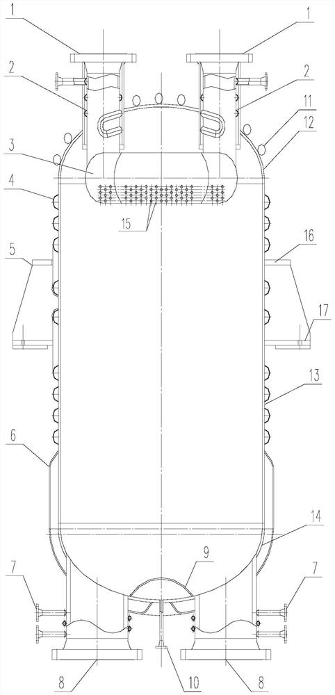
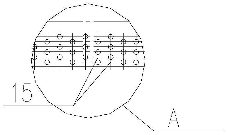
[0018] like figure 1 Shown is the novel devolatilizer of the present invention, which comprises a vertical cylinder, the upper end and the lower end of the cylinder are respectively provided with an upper sealing head 12 and a lower sealing head 14, and a pair of feeding ports 1 are connected to the upper sealing head 12, A pair of discharge ports 8 are connected to the lower head 14 . Inside the cylinder, there is a devolatilization distributor 3 hoisted below the upper head. In order to increase the number of openings of the flow distribution holes on the devolatilization distributor, the devolatilization distributor 3 is formed by connecting a plurality of straight pipes with the same diameter end to end to form a closed outer ring. There are two intermediate connecting pipes communicating with the outer ring pipeline. The lower semicircular pipe wall of the devolatilization distribution pipe is provided with flow distribution holes 15, and the flow distribution holes 15 ...


PUM


Abstract

The invention discloses a novel devolatilization device which comprises a vertical cylinder, an upper end socket and a lower end socket are arranged at the upper end and the lower end of the cylinder respectively, at least one pair of feed ports are connected to the upper end socket, at least one pair of discharge ports are connected to the lower end socket, and a devolatilization distributor hung below the upper end socket is arranged in the cylinder. The devolatilization distributor is a closed outer ring formed by connecting a plurality of devolatilization distribution pipes with the same diameter end to end, a middle connecting pipe communicated with an outer ring pipeline is arranged in an inner ring of the outer ring, flow distribution holes are formed in the lower semicircular pipe wall of each devolatilization distribution pipe, the flow distribution holes are arranged in a triangular mode, the hole diameter ranges from 2 mm to 6 mm, and the devolatilization distributor is provided with an open hole opposite to a feeding port. And the feeding hole is welded and fixed with the devolatilization distributor through the opening and is communicated with the devolatilization distributor through a pipeline By optimizing the inlet and outlet structures of the devolatilization device, optimizing the external heating of the equipment, and optimizing the devolatilization distributor and the flow distribution holes, the devolatilization separation efficiency is improved, and the product quality is further improved.

Description

technical field [0001] The present invention relates to the technical field of devolatilizer equipment. Background technique [0002] The devolatilizer is a device for removing small molecular substances in the polymer. After the polymer enters the devolatilizer, the body surface area of ​​the polymer is increased through the secondary distribution of the devolatilizer by utilizing the different boiling points of different media of the polymer. , the different components of the polymer are gasified and separated, and the unpolymerized gas-phase residual monomer is de-flavored and extracted through the gas-phase outlet by using negative pressure. The devolatilizer is the core equipment to remove the volatile matter in the polymer body and improve the product quality. It is widely used in the production of polystyrene (PS) and ABS devices. [0003] The size of the polymer body extruded from the devolatilization distribution holes directly affects the devolatilization effect. ...

Claims


Application Information

Patent Timeline
Patent Type & Authority Applications(China)
IPC IPC(8): B01D1/00B01D1/30
CPCB01D1/0011B01D1/30Y02P20/10
Inventor 周地张耀均刘贵忠刘凤侠顾广宇何红波杨繁曹盈盈刘怡虹
Owner 广东寰球广业工程有限公司
Why Eureka
Try Eureka