
Device and method for removing nucleic acid pollution

A nucleic acid and hydrochloric acid technology, applied in cleaning methods and utensils, cleaning methods using gas flow, chemical instruments and methods, etc., can solve the problems of insufficient removal, reduced discharge effect, and reduced removal efficiency, etc. Ensure complete removal and improve removal efficiency

Inactive Publication Date: 2022-08-05
李茂宁
View PDF0 Cites 0 Cited by
  • Summary
  • Abstract
  • Description
  • Claims
  • Application Information

AI Technical Summary

Problems solved by technology

[0002] Nucleic acid pollution is a problem that plagues most laboratories; a small amount of nucleic acid pollution will produce false positive test results, which will cause misdiagnosis of patients and delay the treatment of patients; if this situation develops, it will form aerosol pollution and spread, eventually It will lead to the pollution of the whole laboratory, and if it is serious, the laboratory will be closed. If there is no spare laboratory, it will cause greater losses. Therefore, a device for removing nucleic acid contamination is needed; It has a relatively high pressure, so that the gasified hydrochloric acid is discharged slowly, thereby reducing the removal efficiency, and when the gasified hydrochloric acid is discharged, the discharge angle and position cannot be adjusted, and it can only be discharged in a certain direction, so that the gasification Hydrochloric acid spreads for a long time, thereby reducing the discharge effect, and the method of removing nucleic acid contamination is relatively slow, and the removal is not thorough enough, which reduces the removal effect.

Method used


Image

  • Device and method for removing nucleic acid pollution
  • Device and method for removing nucleic acid pollution
  • Device and method for removing nucleic acid pollution

Examples


Embodiment 1

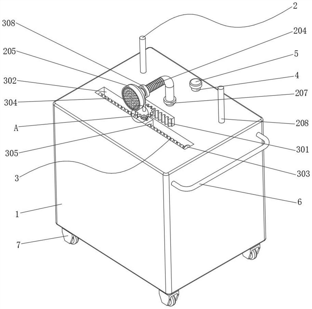
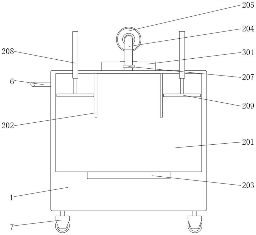
[0031] see figure 1 and image 3 , a device for removing nucleic acid pollution, comprising a work box main body 1, a hydrochloric acid evaporation assembly 2 and an adjustment assembly 3, a hydrochloric acid evaporation assembly 2 is fixed on one side inner wall of the work box main body 1, and a top outer wall of the work box main body 1 is fixed with Adjustment assembly 3; a liquid inlet pipe 4 is connected through the top inner wall of the liquid storage tank 201, a sealing cover 5 is sealed and installed on the top outer wall of the liquid inlet pipe 4, the sealing cover 5 is unscrewed, and then the hydrochloric acid solution is passed through the liquid inlet pipe 4. Put it into the liquid storage tank 201 to improve the feeding effect; a push handle 6 is welded on one side outer wall of the main body 1 of the work box, and a universal wheel 7 is distributed and installed on the outer wall of the bottom end of the main body 1 of the work box, which is controlled by the p...

Embodiment 2

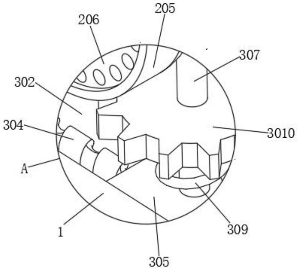
[0035] see figure 2 and Figure 4, the adjustment assembly 3 includes a rack 301, a chute 302, a motor 303, a threaded rod 304, a slider 305, a threaded hole 306, a rotating rod 307, a collar 308, a torsion spring 309 and a gear 3010, the top outer wall of the main body 1 of the work box There is a chute 302 on the upper side, a motor 303 is embedded in the inner wall of one side of the chute 302, a threaded rod 304 is rotatably connected to the inner wall of the other side of the chute 302, and one end of the output shaft of the motor 303 is fixed to the threaded rod 304 A slider 305 is slidably connected to the inner wall of one end of the chute 302, a rotating rod 307 is rotatably connected to the outer wall of the top end of the slider 305, and a collar 308 is sleeved on the outer wall of one side of the telescopic exhaust pipe 204. , and the top outer wall of the rotating rod 307 is fixed on the outer wall of the collar 308, a gear 3010 is welded on one side of the oute...

Embodiment 3

[0038] see Figure 5 , a method for removing nucleic acid pollution, comprising the following steps: step 1, hydrochloric acid gasification; step 2, instrument protection; step 3, steam fumigation; step 4, equipment ventilation; step 5, receiving hydrochloric acid;

[0039] Wherein in the above-mentioned step 1, the concentrated hydrochloric acid is first placed inside the equipment, then the concentrated hydrochloric acid is heated, and the sealed space in the equipment is pressurized, so that the hydrochloric acid is gasified;

[0040] Wherein, in the above-mentioned step 2, the equipment and instruments that are easily reacted with hydrochloric acid are wiped with alcohol, and then the equipment is sealed and protected; in the step 2, the type of alcohol is a 75% anhydrous alcohol;

[0041] Wherein, in the above-mentioned step 3, the vaporized hydrochloric acid is steam fumigated to the equipment inside the laboratory, and then the vaporized hydrochloric acid is reacted wit...


PUM


Abstract

The invention discloses a device and method for removing nucleic acid pollution, the device comprises a working box main body, a hydrochloric acid evaporation assembly and an adjusting assembly, the hydrochloric acid evaporation assembly is fixed on the inner wall of one side of the working box main body, and the adjusting assembly is fixed on the outer wall of the top end of the working box main body; the hydrochloric acid evaporation assembly comprises a liquid storage tank, a partition plate, heating pieces, a telescopic exhaust pipe, an expansion pipe, a ventilation plate, a valve, an air cylinder and a sealing plate, the liquid storage tank is formed in the inner wall of one side of the working box body, and the heating pieces are symmetrically embedded in the inner wall of the bottom end of the liquid storage tank; according to the device, the interior of equipment can be stamped, and when gasified hydrochloric acid is discharged, the gasified hydrochloric acid can be sprayed and discharged to the periphery of a laboratory, so that the gasified hydrochloric acid is rapidly diffused into the laboratory, and the removing efficiency is improved; and the angle and the position of the discharge structure can be adjusted, so that gasified hydrochloric acid is prevented from being discharged only in a certain direction and can be uniformly diffused into a laboratory, and the discharge effect is improved.

Description

technical field [0001] The present invention relates to the technical field of nucleic acid pollution removal, in particular to a device and method for removing nucleic acid pollution. Background technique [0002] Nucleic acid contamination is a problem that plagues most laboratories; trace amounts of nucleic acid contamination will produce false positive test results, which will lead to misdiagnosis of patients and delay their illness; if this situation is allowed to develop, aerosol pollution will form and spread, and eventually This will lead to contamination of the entire laboratory. In severe cases, the laboratory will be closed. If there is no spare laboratory, it will cause greater losses. Therefore, a device to remove nucleic acid contamination is required; however, the existing removal device is generally used when hydrochloric acid is generated. It has a large pressure, so that the gasified hydrochloric acid is discharged slowly, thus reducing the removal efficien...

Claims


Application Information

Patent Timeline
Patent Type & Authority Applications(China)
IPC IPC(8): B08B5/02B08B13/00
CPCB08B5/02B08B13/00
Inventor 谢丽华李茂宁唐薇薇黄治权江映华李象喜韦柳青唐国春陆福强黄秀玲文艳玲范富辉黄绪晓
Owner 李茂宁
Learn More