
Automatic material distribution system

A technology of automatic material distribution and material distribution, which is applied in the direction of unloading devices, unloading devices, manufacturing tools, etc., and can solve problems such as low production efficiency, uneven material distribution, and a large number of manpower

Pending Publication Date: 2022-08-05
SICHUAN JIAOTOU CONSTR ENG CO LTD
View PDF0 Cites 0 Cited by
  • Summary
  • Abstract
  • Description
  • Claims
  • Application Information

AI Technical Summary

Problems solved by technology

[0003] The purpose of the present invention is to provide an automatic material distribution system, which solves the problems of a large amount of manpower, uneven material distribution, and low production efficiency when the box girder is poured.

Method used


Image

  • Automatic material distribution system
  • Automatic material distribution system
  • Automatic material distribution system

Examples


Embodiment Construction

[0034] In order to make the purposes, technical solutions and advantages of the embodiments of the present invention clearer, the technical solutions in the embodiments of the present invention will be clearly and completely described below with reference to the accompanying drawings in the embodiments of the present invention. Obviously, the described embodiments These are some embodiments of the present invention, but not all embodiments. The components of the embodiments of the invention generally described and illustrated in the drawings herein may be arranged and designed in a variety of different configurations.

[0035] Thus, the following detailed description of the embodiments of the invention provided in the accompanying drawings is not intended to limit the scope of the invention as claimed, but is merely representative of selected embodiments of the invention. Based on the embodiments of the present invention, all other embodiments obtained by those of ordinary ski...


PUM


Abstract

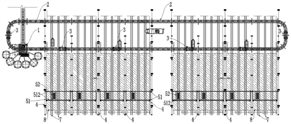
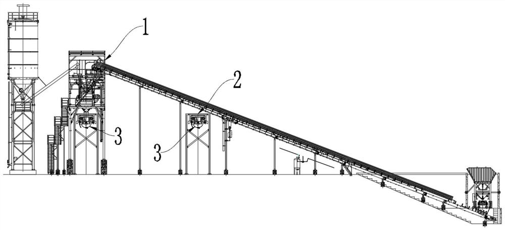
The invention provides an automatic material distributing system which comprises a concrete mixing station, a material conveying track, a feeder, a main track and a material distributing machine, the material conveying track is connected end to end to form a ring shape, the material conveying track passes through a material discharging position of the concrete mixing station, the feeder is movably arranged on the material conveying track, and the main track is connected with the material distributing machine. The material distributing machine is movably arranged on the main track, and the main track is located below the feeding track. The automatic material distribution system equipment triggers material calling at a production line material calling point, a material calling task is formed and issued to a material calling management system of the concrete mixing station, the system interacts with a material ramming system of the concrete mixing station through an interface, and a production record formed by a material ramming program is uploaded to the material calling management system. The problems that a large amount of manpower is needed during box girder pouring, material distribution is uneven, and production efficiency is low are solved.

Description

technical field [0001] The invention relates to the technical field of prefabricated box beams, in particular to an automatic distribution system. Background technique [0002] Box girder, a kind of beam in bridge engineering, is hollow inside, with flanges on both sides of the upper part, similar to a box, hence the name. Single box, multiple boxes, etc. The box girders of reinforced concrete structures are divided into prefabricated box girders and cast-in-place box girders. At present, in order to improve production efficiency and quality, small box girder intelligent prefabrication plants based on smart beam factory intelligent concrete distribution centers and assembly lines are mostly used to prefabricate the required box beams. At present, in the process of prefabricating box girder, most of the operations need manual participation, especially when pouring, the unique U-shaped structure of the box girder requires repeated observation and confirmation manually to ens...

Claims


Application Information

Patent Timeline
Patent Type & Authority Applications(China)
IPC IPC(8): B28B13/02B28B13/06B28B17/00B28B1/087B28B15/00B28C7/16
CPCB28B13/023B28B13/0235B28B17/0072B28B1/0873B28B13/067B28B15/007B28C7/16
Inventor 徐林滕宇刘洋陈智勇李鹏飞
Owner SICHUAN JIAOTOU CONSTR ENG CO LTD
Learn More