
Eureka
For R&D, Eureka makes reading and utilizing patents & technical documents easy.
Eureka AIR
Designed for self-driven R&D workflows. Generate viable solutions, solve complex R&D challenges, empower your innovation with AI.

Eureka Materials
Designed for material experts only. Revolutionize your material R&D, from search, analyze, to developing new materials.

TechResearch
Generate reliable direction feasibility study reports for your R&D in just a few steps.

TechSeek
Discover and master advanced knowledge NOW. Basics, ideas, possibilities, all at once.

TechMind
As an expert in R&D Theories, TechMind can generates customized viable solutions instantly.

TechRisk
Analyze your overall solution with one click, know your potential R&D risks in advance.

TechMonitor
Get weekly tech updates, stay abreast of the latest tech innovations and key insights.
Vibration type carbon cold press molding device
A cold forming and vibrating technology, which is applied in the direction of material forming presses, presses, biofuels, etc., can solve the problem of poor tightness of carbon blanks, inability to extrude high-density spiral carbon tubes, and limited extrusion force and other issues to achieve the effect of improving structural strength and tensile properties
- Summary
- Abstract
- Description
- Claims
- Application Information
AI Technical Summary
Problems solved by technology
Method used
Image

Examples
Embodiment 1
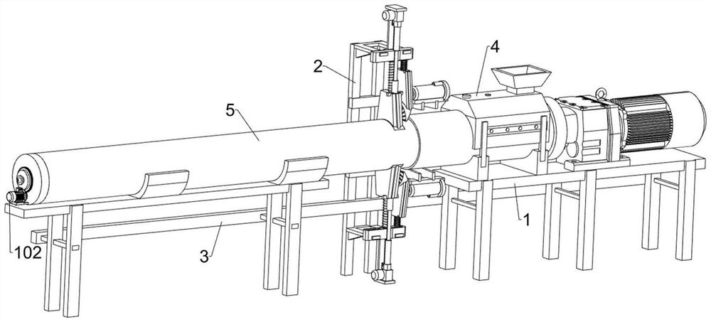
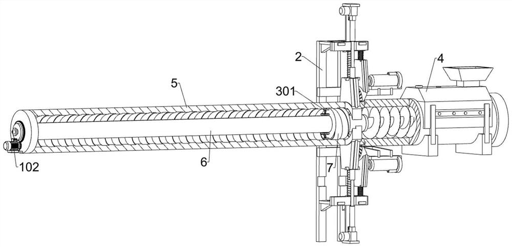
[0032] A vibrating carbon cold press forming device, such as Figure 1-Figure 10As shown, it includes a rotating unit, a cold-pressing forming unit, a vibrating unit, a right chassis 1, a rear bracket 2, a left chassis 3, a screw extruder 4, a forming cylinder 5, an air extraction pipe 6, and a moving retaining ring 7 and taking over 8; the left side of the right bottom frame 1 is fixed with the rear bracket 2; the left side of the rear bracket 2 is fixed with the left bottom frame 3; the upper side of the right bottom frame 1 is installed with a screw extrusion Machine 4; the upper side of the left chassis 3 is placed with a forming cylinder 5; the inner side of the forming cylinder 5 is rotatably connected with an air extraction pipe 6; the upper and lower sides of the air extraction pipe 6 are each provided with a guide groove; Each of the guide grooves is provided with a number of air extraction holes; the right end of the air extraction pipe 6 is slidably connected with a...
Embodiment 2
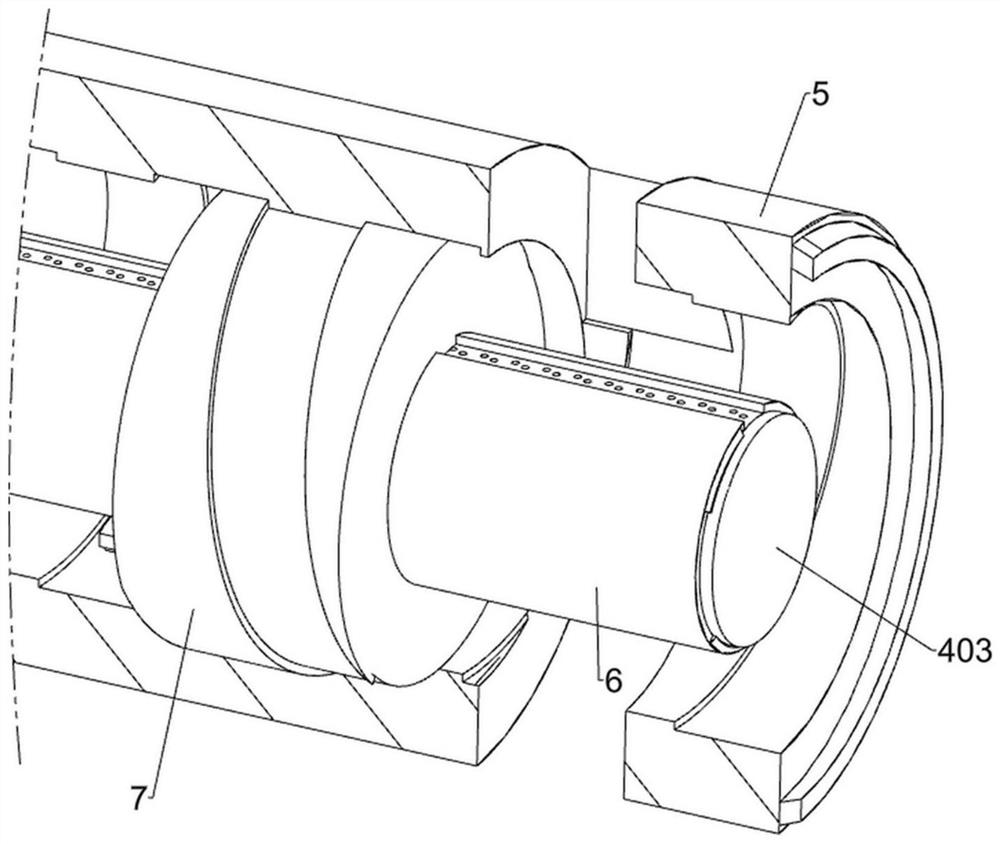
[0044] like Figure 1-Figure 11 As shown, this embodiment is further optimized on the basis of Embodiment 1, and also includes an inner blank trimming unit, the right end of the forming cylinder 5 is provided with an inner blank trimming unit, and the inner blank trimming unit includes a second drive motor 401 , the central shaft 402, the rotary plate 403 and the trimming knife 404; the inner side of the forming cylinder 5 is bolted with a second driving motor 401; the right end of the forming cylinder 5 is rotatably connected with the central shaft 402; the output shaft of the second driving motor 401 is fixedly connected The central shaft 402 ; the right end of the central shaft 402 is fixedly connected with a rotary plate 403 ;
[0045] The carbon blank formed in the forming cylinder 5 has a long structure corresponding to the guide grooves on both sides of the exhaust pipe 6 on the upper part of the inner side and the lower part of the inner side respectively. During the ...
PUM
 Abstract
Description
Claims
Application Information
 - R&D Engineer
- R&D Manager
- IP Professional
- Industry Leading Data Capabilities
- Powerful AI technology
- Patent DNA Extraction
Browse by: Latest US Patents, China's latest patents, Technical Efficacy Thesaurus, Application Domain, Technology Topic, Popular Technical Reports.
© 2024 PatSnap. All rights reserved.Legal|Privacy policy|Modern Slavery Act Transparency Statement|Sitemap|About US| Contact US: help@patsnap.com