Ventilation and smoke exhaust system of tunnel

A smoke exhaust system and tunnel technology, which is used in mine/tunnel ventilation, climate sustainability, mining equipment, etc., can solve construction difficulties, large pressure difference between lane and smoke exhaust pipe, and increase in negative pressure value of smoke exhaust pipe and other problems, to achieve the effect of reducing the difficulty of construction technology, saving civil construction and installation costs, and improving smoke exhaust power

Pending Publication Date: 2022-08-09
CHINA RAILWAY FIFTH SURVEY & DESIGN INST GRP
View PDF0 Cites 0 Cited by
  • Summary
  • Abstract
  • Description
  • Claims
  • Application Information

AI Technical Summary

Problems solved by technology

[0004] However, when the length of the tunnel is longer, on the one hand, the number of exhaust outlets on the exhaust path increases, resulting in an increase in the resistance of the exhaust system pipe network and the negative pressure value of the exhaust pipeline, which makes the pressure difference between the driveway and the exhaust pipeline too large. As a result, the air leakage at the construction joints of the smoke exhaust pipeline increases, which not only increases the purchase and installation costs of the smoke exhaust damper, but also causes the failure of the fixed-point smoke exhaust system and reduces the reliability of the smoke exhaust system
On the other hand, the number of smoke exhaust shafts and tunnel machine rooms has increased, leading to construction difficulties, long construction periods and increased construction risks, which have increased civil engineering and mechanical and electrical construction and installation costs by tens of millions.

Method used


Image

  • Ventilation and smoke exhaust system of tunnel
  • Ventilation and smoke exhaust system of tunnel
  • Ventilation and smoke exhaust system of tunnel

Examples


Embodiment 1

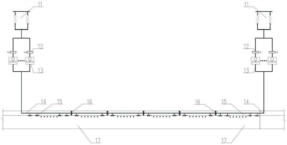
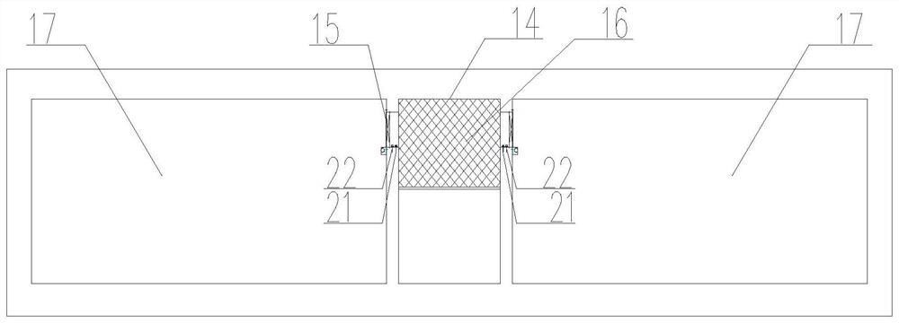
[0066] like figure 1 , figure 2 , image 3 , Figure 4 and Figure 5 As shown, a ventilation and smoke exhaust system for a tunnel includes:

[0067] The end smoke exhaust device is arranged at the end of the exhaust air duct 14 of the tunnel;

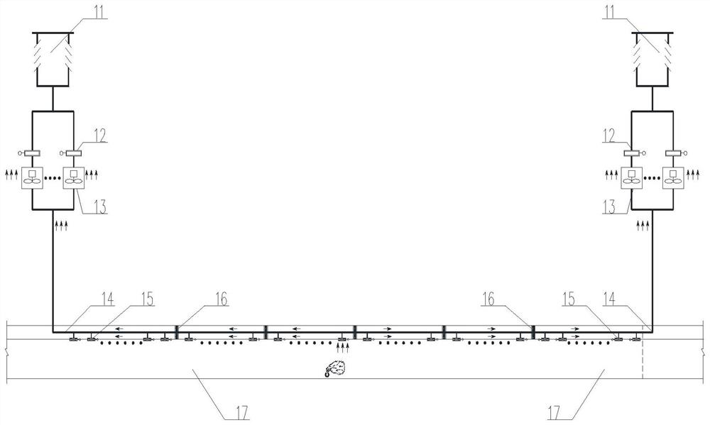
[0068] A plurality of exhaust duct relay devices 16 are arranged at intervals in the exhaust air duct 14 of the tunnel. The exhaust duct relay devices 16 are used to blow the exhaust air duct in sections to increase the pressure in the exhaust air duct, and are connected to the end exhaust duct. The fume devices jointly discharge the flue gas in the flue gas duct 14 out of the flue gas duct.

[0069] The ventilation and smoke exhaust system of the tunnel according to the embodiment of the present application includes two end smoke exhaust devices and a plurality of exhaust flue relay devices. The two end smoke exhaust devices are respectively arranged at both ends of the smoke exhaust air duct. A plurality of flue exhaust duct ...


PUM


Abstract

The embodiment of the invention provides a ventilation and smoke exhaust system of a tunnel, which comprises an end smoke exhaust device arranged at the end of a smoke exhaust air duct of the tunnel; and the multiple discharge flue relay devices are arranged in a smoke discharge air flue of the tunnel at intervals, the discharge flue relay devices are used for blowing air to the smoke discharge air flue in a segmented mode to increase the pressure in the smoke discharge air flue, and the discharge flue relay devices and the end smoke discharge devices jointly discharge smoke in the smoke discharge air flue out of the smoke discharge air flue. According to the embodiment of the invention, the smoke exhaust duct relay device is mounted in the smoke exhaust duct, and the end smoke exhaust device is mounted at the end of the smoke exhaust duct, so that a fixed-point smoke exhaust function is formed, the problem that the negative pressure value of the smoke exhaust duct is increased when a smoke exhaust duct pipeline is relatively long is effectively solved, the pipe network resistance of the smoke exhaust system is reduced, and the service life of the smoke exhaust system is prolonged. The problem that the smoke exhaust system fails due to the fact that the air speed of the smoke exhaust opening is too large in the near-end ignition working condition of the smoke exhaust air duct is solved, and the reliability and intelligence of the ventilation and smoke exhaust system are improved.

Description

technical field [0001] The present application relates to the technical field of ventilation and smoke exhaust, and in particular to a ventilation and smoke exhaust system for a tunnel. Background technique [0002] A tunnel is a channel set in a mountain or underground. Due to the linear engineering of underwater tunnels and mountain tunnels, when passing railway trains, subway vehicles, cars and people, due to ground or mountain conditions, emergencies often occur. The tunnel is closed. In order to ensure the safety of the vehicle operators in the tunnel and provide guarantee for the evacuation of passengers, a ventilation and smoke exhaust system must be installed in the tunnel to adjust the air circulation in the tunnel and ensure the safety of vehicle personnel. [0003] In the existing ventilation and smoke exhaust system, a flue gas exhaust duct and a smoke exhaust air valve are usually arranged inside the tunnel along the direction of the tunnel. The flue gas from t...

Claims


Application Information

Patent Timeline
Patent Type & Authority Applications(China)
IPC IPC(8): E21F1/00E21F1/04E21F1/08E21F1/14E21F17/18
CPCE21F1/003E21F1/04E21F1/08E21F1/145E21F17/18Y02B30/70
Inventor 梁园罗章波何明华谌启发崔志强于晓波王威李清瑞付凯赵超峰张宇黄新连邱浩王旭明唐玉川蔡薇薇
Owner CHINA RAILWAY FIFTH SURVEY & DESIGN INST GRP
Why Eureka
Try Eureka