
Low-temperature fixed ball valve

A fixed ball valve, low temperature technology, applied in the valve device, valve details, valve shell structure and other directions, can solve the problems of increasing manufacturing and procurement costs, incompetence, sealing failure, etc., to reduce the cost of manufacturing and use, and improve the service life effect.

Active Publication Date: 2022-08-09
CHENGDU CHENGGAO VALVE +2
View PDF6 Cites 4 Cited by
  • Summary
  • Abstract
  • Description
  • Claims
  • Application Information

AI Technical Summary

Problems solved by technology

[0006] In order to meet the requirement that both the upstream seat assembly and the downstream seat assembly can withstand the medium pressure from the upstream end and from the downstream end, and the valve cavity must be able to release pressure; therefore, the existing cryogenic ball valve structure is: the upstream seat assembly adopts a lip The seal ring seals the medium pressure from the upstream end. When the valve cavity is overpressured, the pressure is released to the downstream end through the upstream lip seal ring; the downstream end valve seat adopts a double-piston lip seal ring or installs two lip seal rings in the opposite direction. In order to achieve two-way sealing, seal the medium pressure from the downstream end and the pressure from the valve cavity; but this structure has flow direction requirements for the medium, requiring the medium to flow from the upstream end to the downstream end, initially with the upstream end valve seat assembly Seal, only at the upstream end When the seal of the seat assembly fails, the medium pressure enters the valve cavity and pushes the seat assembly at the downstream end to seal, so that the sealing effect of both the upstream seat assembly and the downstream seat assembly can be achieved; If the downstream end valve seat seal fails, the medium enters the valve chamber, and the upstream valve seat assembly uses a lip seal ring that can only seal in one direction and cannot seal the valve from the valve. Cavity pressure, at this time the sealing of the entire valve fails
[0007] In the existing cryogenic ball valve, when the valve chamber is heated up or flashed, the overpressure is released through the deformation of the lip seal ring of the upstream valve seat assembly, and the lip seal ring is easily deformed under repeated pressure during pressure relief. The shrinkage of the parts in the low temperature environment will cause the sealing failure of the lip seal ring of the upstream valve seat assembly; while the downstream valve seat will be damaged by the erosion of the medium during the process of opening or closing the valve, causing the seal to fail. Once the downstream valve seat Sealing failure, the upstream lip seal cannot play a sealing role due to frequent pressure relief, and both the upstream seat assembly and the downstream seat assembly will fail to seal, thus shortening the service life of the entire valve
Moreover, due to the double-piston lip seals used in the valve seat at the downstream end or two lip seals installed backwards, the components of the upstream valve seat assembly and the downstream valve seat assembly are different and cannot be used in common, which will increase the manufacturing cost. purchase cost

Method used


Image

  • Low-temperature fixed ball valve
  • Low-temperature fixed ball valve
  • Low-temperature fixed ball valve

Examples


Embodiment Construction

[0040] In order to make the purposes, technical solutions and advantages of the embodiments of the present invention clearer, the technical solutions in the embodiments of the present invention will be clearly and completely described below with reference to the accompanying drawings. Obviously, the described embodiments are some, but not all, embodiments of the present invention.

[0041] Accordingly, the following detailed descriptions of embodiments of the present invention are not intended to limit the scope of the claimed invention, but merely represent some embodiments of the present invention. Based on the embodiments of the present invention, all other embodiments obtained by those of ordinary skill in the art without creative efforts shall fall within the protection scope of the present invention.

[0042] It should be noted that the embodiments of the present invention and the features and technical solutions of the embodiments may be combined with each other unless ...


PUM


Abstract

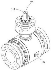
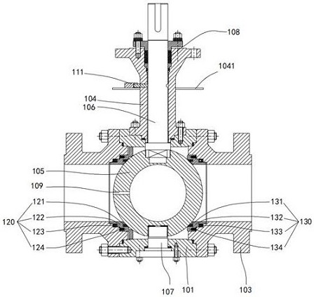
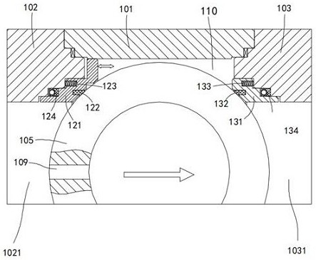
A ball core is arranged in a main valve body, a first valve body and a second valve body are arranged on the two sides of the main valve body, the low-temperature fixed ball valve is provided with a first valve seat assembly and a second valve seat assembly, the valve seat assembly is provided with a first valve seat support, a first lip-shaped sealing ring and a first valve seat, the first valve seat support is provided with a pressure-bearing check ring, and the second valve seat support is provided with a second lip-shaped sealing ring. A sealing switching hole is formed in the ball core, during working, the sealing switching hole faces the upstream, the first valve seat assembly does not participate in sealing, a pressure medium enters the second valve seat assembly through the sealing switching hole, the second valve seat assembly plays a sealing role, when the second valve seat assembly loses efficacy, the sealing switching hole is switched to the downstream side, the first valve assembly plays a sealing role, and meanwhile, the second valve seat assembly is switched to the downstream side. The ball valve is provided with the audible and visual alarm, an operator can be reminded to switch the two sets of sealing assemblies or replace a failure assembly in time, the ball valve is further provided with the reverse rotation preventing device, the rotation range of the valve rod can be limited, and the situation that an incorrect sealing assembly is used for sealing is avoided.

Description

technical field [0001] The patent of the present invention relates to the technical field of valves, in particular to a low temperature fixed ball valve. Background technique [0002] Low temperature fixed ball valves are mainly used in low temperature media such as liquefied natural gas (LNG), liquefied petroleum gas, liquid oxygen, liquid hydrogen, etc. These media are not only flammable and explosive, but also gasify when heating up or flashing, and the volume of gasification is sharp. Expansion, the ball valve that transports these fluids has a closed valve cavity and an unreasonable structural design, which will cause overpressure in the valve cavity, resulting in medium leakage, and even ball valve cracking and accidents. Since the O-ring is not resistant to low-temperature media, the existing low-temperature ball valves are all sealed with a lip seal, and rely on the one-way sealing feature of the lip seal, when the valve cavity is overpressured, it passes through the...

Claims


Application Information

Patent Timeline
Patent Type & Authority Applications(China)
IPC IPC(8): F16K5/06F16K5/20F16K5/10F16K27/06F16K35/02F16K35/10F16K35/16F16K37/00F16J15/3208F16J15/3268G01M3/28
CPCF16K5/0605F16K5/0647F16K5/0689F16K5/201F16K5/10F16K27/067F16K37/0008F16K37/005F16K35/027F16K35/16F16K35/10F16J15/3208F16J15/3268G01M3/2876
Inventor 王启全冯科张海林李俊霖姜涛白开玉曾品其张朝东杨智林长洪
Owner CHENGDU CHENGGAO VALVE
Learn More