Straightness detection device for geological exploration drill rod

A technology for geological exploration and detection devices, which is applied to measurement devices, optical devices, workpiece clamping devices, etc., can solve problems such as low detection efficiency, poor detection accuracy, and inability to detect inclination, and improve detection efficiency and detection range. boosted effect

Active Publication Date: 2022-08-09
LANZHOU CITY UNIV
View PDF7 Cites 3 Cited by
  • Summary
  • Abstract
  • Description
  • Claims
  • Application Information

AI Technical Summary

Problems solved by technology

[0003] Chinese invention patent 2017100643349 relates to a straightness calibration mechanism for geological exploration drill pipes, including a frame plate. The upper surface of the frame plate is symmetrically equipped with a plurality of contact sensing devices, support devices and feeding devices, and the frame plate The front side is fixedly connected with a material guide plate, a material shifting device and a storage rack; the contact sensing devices are evenly distributed on the frame plate, and the supporting device and the discharging device are symmetrically separated on the upper surface of the frame plate in the length direction At both ends, the feeding device is located between the two supporting devices. The straightness calibration mechanism of the geological exploratio

Method used


Image

  • Straightness detection device for geological exploration drill rod
  • Straightness detection device for geological exploration drill rod
  • Straightness detection device for geological exploration drill rod

Examples


no. 1 example

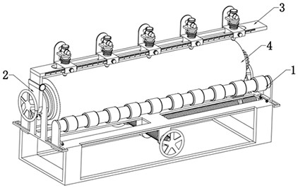
[0041] like Figure 1 to Figure 10 As shown, a straightness detection device for a drill pipe for geological exploration includes a support assembly 1, a clamping assembly 2, a detection assembly 3 and a drill pipe body 4. The clamping assembly 2 is arranged on both ends of the upper surface of the support assembly 1, and the clamping assembly 2 The top of the holding assembly 2 is provided with a detection assembly 3 , and the middle of the upper surface of the supporting assembly 1 is provided with a drill rod body 4 , which is clamped by the clamping assembly 2 .

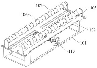
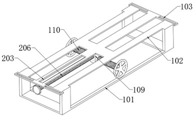
[0042] Support assembly 1, the support assembly 1 includes a support frame 101, the upper surface of the support frame 101 is provided with a support frame 102, the four corners of the support frame 102 are provided with through grooves 103, the through grooves 103 are arranged in a strip structure, and the support frame 102 The lower surface of the movable plate 104 is provided with two symmetrically distributed...

no. 2 example

[0055] like Figure 11 As shown, when the drill pipe body 4 is inspected, especially if the position of the drill pipe body 4 is convex or concave, the vertical support rod 106 and the elastic roller 107 cannot have the required supporting effect on the drill pipe body 4 At the same time, when the drill rod body 4 is rotated to detect the straightness, the convex or concave position of the drill rod body 4 is limited to the support rod 106 and the elastic roller 107, so that it cannot be further rotated and calibrated. In order to solve the above problems, The straightness detection device for a drill pipe for geological exploration further includes: a controller is provided on one side of the support assembly 1 , the controller is mainly arranged on one side of the support frame 101 , and the controller electrically controls each electrical element.

[0056] The light transmittance of the light-transmitting lens 316 gradually decreases from top to bottom, and the other end of...


PUM


Abstract

The invention discloses a straightness detection device for a geological exploration drill rod, and relates to the technical field of drill rod detection equipment, the straightness detection device comprises a supporting assembly, clamping assemblies, a detection assembly and a drill rod body, the clamping assemblies are arranged at the two ends of the upper surface of the supporting assembly, and the detection assembly is arranged at the top ends of the clamping assemblies; a drill rod body is arranged in the middle of the upper surface of the supporting assembly, the supporting assembly can support the drill rod, the clamping assembly is arranged above the supporting assembly, the clamping assembly can clamp the two ends of the drill rod, the drill rod can be driven to rotate through the clamping assembly, and the drill rod can be clamped through the clamping assembly. The detection assembly is arranged at the top end of the clamping assembly, the detection assembly can detect multiple parts of the outer side of the drill rod, the supporting assembly, the clamping assembly and the detection assembly are matched, multi-directional rapid detection of the drill rod can be achieved, compared with manual detection, the detection efficiency can be effectively improved, and the drill rod detection device is more suitable for rapid detection of multiple drill rods.

Description

technical field [0001] The invention relates to the technical field of drill pipe detection equipment, in particular to a straightness detection device of a geological exploration drill pipe. Background technique [0002] Drill pipe is a steel pipe with a thread at the end, which is used to connect the surface equipment of the drilling rig and the drilling and grinding equipment or bottom hole device at the bottom of the well. The purpose of the drill pipe is to transport the drilling mud to the drill bit and together with the drill bit raise, lower or rotate the bottom hole device. Drill pipe must be able to withstand enormous internal and external pressure, twisting, bending and vibration. In the process of oil and gas extraction and refining, drill pipe can be used many times. Drill pipe is divided into three categories: kelly, drill pipe and weighted drill pipe. Drill pipe is an important part of exploration drilling rig. In order to ensure the normal use of drill pipe...

Claims


Application Information

Patent Timeline
IPC IPC(8): G01B11/27G01B11/30B25B11/00
CPCG01B11/27G01B11/30B25B11/00
Inventor 刘璎胡浩马东旭易凯欧阳征健高磊
Owner LANZHOU CITY UNIV
Why Eureka
Try Eureka