
Large-view-field wide-spectrum integrated laser alarm device

A laser warning and wide-spectrum technology, which is applied in the direction of optical device exploration, can solve the problems of no improvement in detection accuracy, small detection band range, and low system integration, so as to facilitate the extraction of light spot information, improve measurement accuracy, and reduce The Effect of False Alarms and False Alarms on Small Systems

Pending Publication Date: 2022-08-09
ZHONGBEI UNIV
View PDF0 Cites 0 Cited by
  • Summary
  • Abstract
  • Description
  • Claims
  • Application Information

AI Technical Summary

Problems solved by technology

There are many existing laser warning technologies, mainly using quadrant photodetectors to measure the angle of the incident laser light. However, in most cases, this method has a limited field of view and a low angular resolution, and it is harmful to the background. Sensitivity and beam irradiance distribution have a strong dependence on
There is also a new method based on the combination of a one-dimensional linear detector and a free-form surface mirror. This method ensures a constant angular resolution throughout the detection field of view, but the detection accuracy achieved by this method is low, and the detectable waveband small range
There is also a detection method based on a fisheye lens and a sinusoidal amplitude grating. Although this method can achieve a large field of view detection, it still does not improve the detection accuracy, and the system integration is not high.

Method used


Image

  • Large-view-field wide-spectrum integrated laser alarm device
  • Large-view-field wide-spectrum integrated laser alarm device
  • Large-view-field wide-spectrum integrated laser alarm device

Examples


Embodiment Construction

[0042] In order to make the purposes, technical solutions and advantages of the embodiments of the present invention clearer, the technical solutions in the embodiments of the present invention will be described clearly and completely below. Obviously, the described embodiments are only part of the embodiments of the present application, not All embodiments, these descriptions are only to further illustrate the features and advantages of the present invention, rather than to limit the claims of the present invention; based on the embodiments in this application, those of ordinary skill in the art can obtain without creative work. All other embodiments belong to the scope of protection of the present application.

[0043] The specific embodiments of the present invention will be described in further detail below with reference to the accompanying drawings and embodiments. The following examples are intended to illustrate the present invention, but not to limit the scope of the ...


PUM

PropertyMeasurementUnit
Grating constantaaaaaaaaaa
Slit widthaaaaaaaaaa

Abstract

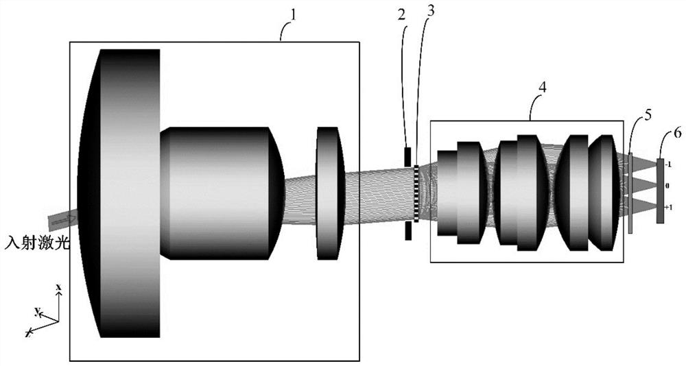
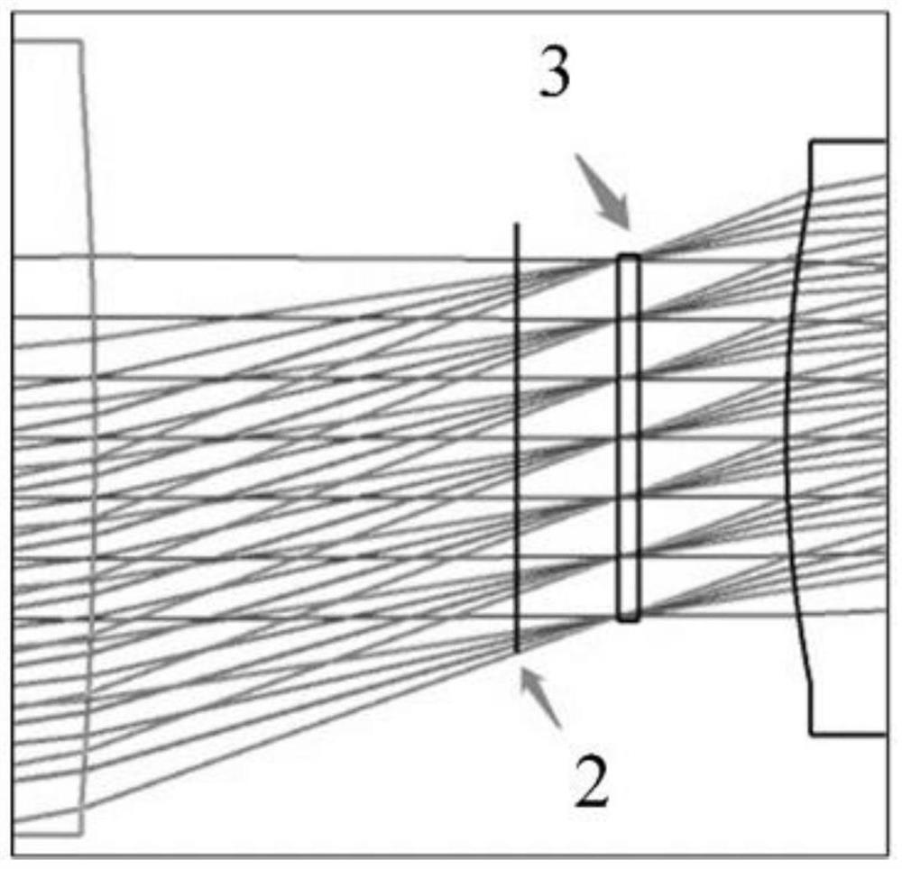
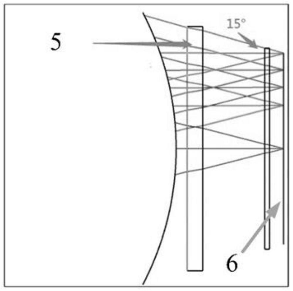
The invention belongs to the technical field of laser warning devices, and particularly relates to a large-view-field wide-spectrum integrated laser warning device which is characterized in that a diaphragm is arranged in the light path direction of a view field compression system, a grating is arranged in the light path direction of the diaphragm, a rear lens is arranged in the light path direction of the grating, and the rear lens is arranged in the light path direction of the grating. A narrow-band optical filter is arranged in the light path direction of the rear lens, and an area array detector is arranged in the light path direction of the narrow-band optical filter. The grating and the multi-band-pass narrow-band optical filter are integrated in the optical lens, diffraction signals are obtained in combination with the area array detector, the grating is tightly attached to the position of the diaphragm so as to reduce vignetting, it is guaranteed that the light fluxes of incident light in different directions passing through the grating are the same, the diffracted light enters the lens and the area array detector, and the light transmittance is improved. The same 0-level and + / -1-level diffraction spot energy of incident light at different angles is realized, and missed alarm and false alarm in a large field of view are avoided.

Description

technical field [0001] The invention belongs to the technical field of laser warning devices, and in particular relates to an integrated laser warning device with a large field of view and a wide spectrum. Background technique [0002] With the continuous advancement of scientific and technological means, laser weapons occupy an important position in the military field, and also pose a great threat to my country's military strategy. Therefore, detecting the incident angle and wavelength of incoming lasers is very important for military security systems. There are many existing laser warning technologies, mainly using quadrant photodetectors to measure the angle of incident laser light. However, in most cases, the field of view detected by this method is limited, the angular resolution is also very low, and the background Sensitivity and beam irradiance distribution have a strong dependence. There is also a new method based on the combination of a one-dimensional linear dete...

Claims


Application Information

Patent Timeline
IPC IPC(8): G01V8/10
CPCG01V8/10
Inventor 张瑞杨雪梅王志斌李孟委
Owner ZHONGBEI UNIV
Learn More