Electrode fixing assembly and dry etching equipment

A technology of fixed components and dry etching, which is applied in the manufacture of electrical components, semiconductor/solid-state devices, circuits, etc. It can solve the problems of particle pollution in the reaction chamber environment, decrease in product yield, and increase in production costs, so as to avoid bad etching , Eliminate particulate matter, improve the effect of product yield

Pending Publication Date: 2022-08-09
SHENZHEN CHINA STAR OPTOELECTRONICS SEMICON DISPLAY TECH CO LTD
View PDF0 Cites 0 Cited by
  • Summary
  • Abstract
  • Description
  • Claims
  • Application Information

AI Technical Summary

Problems solved by technology

[0004] In dry etching equipment, there is usually an electrode fixing seat between the equipment body and the upper electrode. When the upper electrode, the electrode fixing seat and the equipment body are fixedly connected, the upper electrode can be fixed on the equipment body; however, In the existing dry etching equipment, when there is friction between the electrode holder and the equipment body, the surface of the electrode holder is easily worn to cause particles (Particles), which will pollute the environment in the reaction chamber. When it falls on the substrate, the part covered by the particles on the substrate cannot be etched by the plasma, resulting in poor etching, resulting in a decrease in product yield and an increase in production costs

Method used


Image

  • Electrode fixing assembly and dry etching equipment
  • Electrode fixing assembly and dry etching equipment
  • Electrode fixing assembly and dry etching equipment

Examples


Embodiment Construction

[0031] The technical solutions in the embodiments of the present application will be clearly and completely described below with reference to the accompanying drawings in the embodiments of the present application. Obviously, the described embodiments are only a part of the embodiments of the present application, but not all of the embodiments. Based on the embodiments in this application, all other embodiments obtained by those skilled in the art without creative efforts shall fall within the protection scope of this application.

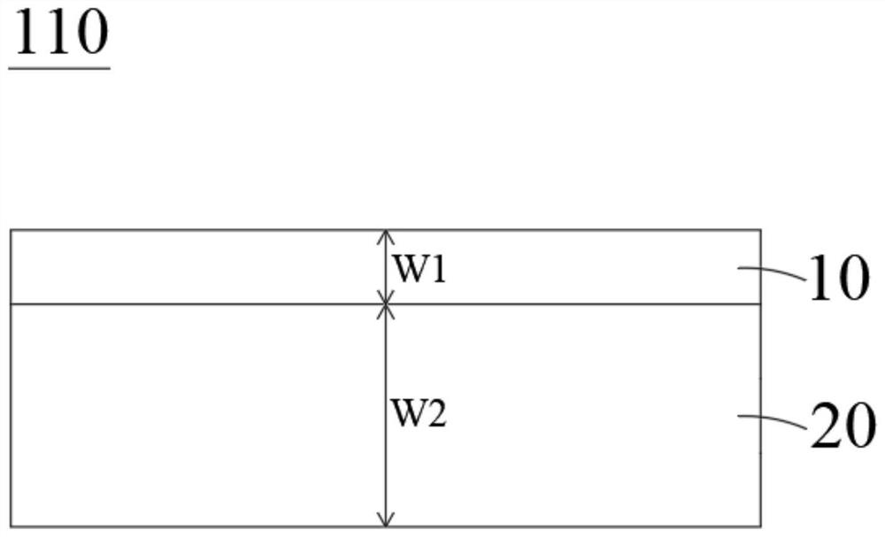
[0032] see figure 1 , figure 1 It is a schematic side view of the electrode fixing assembly provided in the embodiment of the present application. The embodiment of the present application provides an electrode fixing assembly 110 , including a first fixing member 10 and a second fixing member 20 , wherein the hardness of the material of the first fixing member 10 is greater than the hardness of the material of the second fixing member 20 .

[0...


PUM

PropertyMeasurementUnit
thicknessaaaaaaaaaa

Abstract

The embodiment of the invention provides an electrode fixing assembly and dry etching equipment. The electrode fixing assembly comprises a first fixing piece and a second fixing piece, and the hardness of the material of the first fixing piece is larger than that of the material of the second fixing piece; the electrode fixing assembly is used for being arranged in the dry etching equipment to fix an upper electrode on an equipment body, the first fixing piece and the second fixing piece are both arranged between the upper electrode and the equipment body, the side, away from the second fixing piece, of the first fixing piece is arranged towards the equipment body, and the second fixing piece is arranged between the first fixing piece and the second fixing piece. The side, away from the first fixing piece, of the second fixing piece faces the upper electrode. When friction occurs between the electrode fixing assembly and the equipment body, the surface of the electrode fixing assembly is not easy to wear, so that particulate matters can be reduced or eliminated, the problems of poor etching and the like caused by the fact that the substrate to be etched is covered by the particulate matters are avoided, the product yield is improved, and the production cost is reduced.

Description

technical field [0001] The present application relates to the technical field of etching, and in particular, to an electrode fixing assembly and dry etching equipment. Background technique [0002] In the field of display technology, the substrate is usually etched by a dry etching process to produce a corresponding pattern. Specifically, the substrate to be etched is placed in a dry etching equipment, and plasma discharge is used to Etching is performed by removing the material to be etched on the substrate. [0003] The dry etching equipment mainly includes: an equipment body, an upper electrode and a lower electrode located in the reaction chamber of the equipment body, and a base for placing the substrate on the lower electrode; in the specific implementation, the substrate to be etched is placed on the On the base above the lower electrode, the plasma gas is introduced into the reaction chamber to seal the reaction chamber, and a voltage is applied to the upper electro...

Claims


Application Information

Patent Timeline
Patent Type & Authority Applications(China)
IPC IPC(8): H01J37/32H01L21/67
CPCH01L21/67069H01J37/3255H01J37/32568H01J37/32477
Inventor 李智远曾宪甫
Owner SHENZHEN CHINA STAR OPTOELECTRONICS SEMICON DISPLAY TECH CO LTD
Why Eureka
Try Eureka